Ligament force detection system

a detection system and ligament technology, applied in the field of ligament treatment, can solve the problems of difficult handling, high cost, and energy supply requirements of conventional systems, and achieve the effects of improving accuracy, and improving the accuracy of measurement results

Inactive Publication Date: 2006-04-20
BRAINLAB
View PDF11 Cites 38 Cited by
  • Summary
  • Abstract
  • Description
  • Claims
  • Application Information

AI Technical Summary

Benefits of technology

[0012] In accordance with another embodiment, the two outer bodies can be connected to each other at an adjustable distance, and the two pairs of stretcher extensions can extend substantially parallel and substantially in the same direction. The latter feature, for example, can be realized by arranging the pairs of stretcher extensions such that they a...

Problems solved by technology

Such systems have the disadvantage that the sensors are arranged in an insert, e.g., in the portion between the bone structures, and typically transmit their signals, i.e., force or tension data, via a line or wires (e.g. ...

Method used


Image

  • Ligament force detection system
  • Ligament force detection system
  • Ligament force detection system

Examples


Embodiment Construction

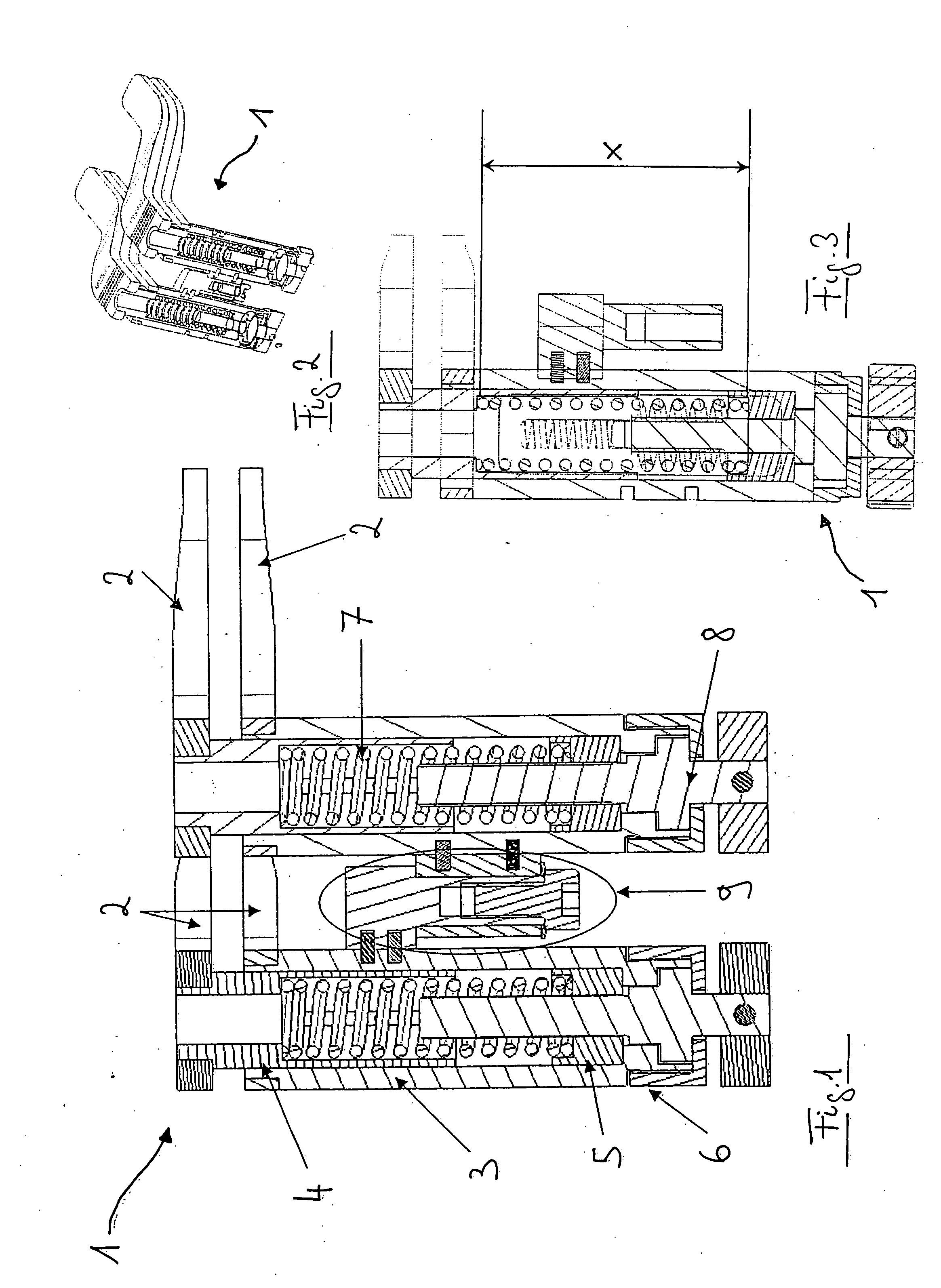
[0022] Referring to FIG. 1, there is provided a section view of an insert 1 of an exemplary ligament force detection system in accordance with the invention. As noted above, the insert also is referred to herein as a ligament balancing device 1.

[0023] The device 1 includes an outer body or outer sleeve 3 that surrounds the mechanism within. An upper inner sleeve 4 and a lower inner sleeve 5 are guided in the outer sleeve 3, and a spring 7 is inserted between the two inner sleeves 4 and 5 (numbering in the right-hand part of the device 1 is embodied in substantially the same way as the left-hand part of the device). A base part 6 is provided beneath the inner sleeve 5 and the outer sleeve 3 and is fastened to the outer sleeve 3 via a threaded fastener, for example. The base part 6 secures a thumb screw 8, which can adjust the length of the spring 7 via a helical gear (not shown). The adjustment is performed by rotating the thumb screw 8, which lifts or lowers the inner sleeve 5 upwa...


PUM


Abstract

A ligament force detection system includes a device configured to be inserted between two body structures connected by ligaments, wherein the device exhibits a predetermined elasticity, and a medical navigation system. The medical navigation system, which is capable of detecting shifts in the body, determines forces acting on the ligaments based on shifts in the body structures and the elasticity of the device.

Description

RELATED APPLICATION DATA [0001] This application claims priority of U.S. Provisional Application No. 60 / 620,812 filed on Oct. 21, 2004, which is incorporated herein by reference in its entirety.FIELD OF THE INVENTION [0002] The invention relates to treating ligaments and, more particularly, to a ligament force detection system. BACKGROUND OF THE INVENTION [0003] In the field of medicine, ligament force detection systems serve to hold body structures, such as bone structures, tensed apart, wherein forces that arise in the ligaments can be defined. The corresponding forces are to be aligned, for example, when ligament structures are manipulated, in order to restore the anatomical position of an axis, such as a leg axis. This is particularly applicable to cases in which joint prostheses are inserted. [0004] Force and / or tension sensors are described in U.S. Pat. No. 5,470,354 and in European patent application EP 1 402 857 A2, wherein a provisional tibial component comprising an inbuil...

Claims


Application Information

Patent Timeline
IPC IPC(8): G01N3/08
CPCG01N3/08G01N2203/0017G01N2203/0676G01N2203/0682
Inventor NEUBAUER, TIMOPLASSKY, NORMANWAGNER, BENJAMIN
Owner BRAINLAB
Why Eureka
Try Eureka