Die device

a technology of dies and parts, applied in the direction of metal working apparatus, manufacturing tools, shaping tools, etc., can solve the problem of difficulty in grasping the repolishing quantity of the punch blade portion, and achieve the effect of easy attachment and removal

Inactive Publication Date: 2006-04-20
AMADA CO LTD
View PDF9 Cites 22 Cited by
  • Summary
  • Abstract
  • Description
  • Claims
  • Application Information

AI Technical Summary

Benefits of technology

[0012] In other words, when the retainer collar freely turns with respect to the punch guide and is rotated with respect to the punch guide, the upper punch driver piercing the retainer collar movably up and down is rotated with respect to the punch guide. As a result, since the upper punch driver is screwed into the lower punch driver and the is rotated with respect to the lower punch driver provided on the punch guide movably up and down, an up-down positional relationship between the upper punch driver and the lower punch driver is changed so that a punch height can be adjusted.
[0013] In the die device based on a second aspect depending from the first aspect, an engagement concave portion is provided in a vicinity of an outer peripheral portion of the retainer collar in a peripheral direction; and a latch member, which is maintained so as to be freely engaged with and disengaged from the engagement concave portion and normally in a engaged state, is provided on the upper portion of the punch guide in a diametrical direction so as to freely move.
[0015] In other words, in the normal state, the latch portion, which is provided on the upper portion of the punch guide movably to the center in the diametrical direction, is engaged with the engagement concave portion provided in the vicinity of the outer peripheral portion of the retainer collar in the peripheral direction, so that the retainer collar is disabled to rotate with respect to the punch guide. Meanwhile, when the punch height is adjusted, the latch member is moved to the inside in the diameterical direction so as to be disengaged from the engagement concave portion of the retainer collar, so that the retainer collar is enabled to rotate with respect to the punch guide. For this reason, when the retainer collar is rotated relatively with respect to the punch guide, the up-down positional relationship between the upper punch driver and the lower punch driver is easily adjusted so that the punch height can be adjusted.
[0024] In a die device based on an eleventh aspect depending from the tenth aspect, an upper surface of the upper punch body or a lower surface of the punch driver is provided with an elastic member for preventing close contact between the upper surface and the lower surface.
[0027] As understood from the explanation of the above configuration, according to the third through thirteenth aspect of the present invention, the stripper plate can be attached and detached easily, and the stripper plate can be fixed to be held securely. Moreover, the repolishing of the punch blade portion and the height adjustment after that are easy, and the above-mentioned conventional problems can be solved.

Problems solved by technology

In the above configuration, although the height adjustment after repolishing of the punch blade portion can be made easily, it is difficult to grasp a repolishing quantity of the punch blade portion, and the internal thread portion and the external thread portion are occasionally screwed firmly at the time of assembly after the repolishing.

Method used


Image

  • Die device
  • Die device
  • Die device

Examples


first embodiment

[0039] There will be explained below a die device of the present invention as a

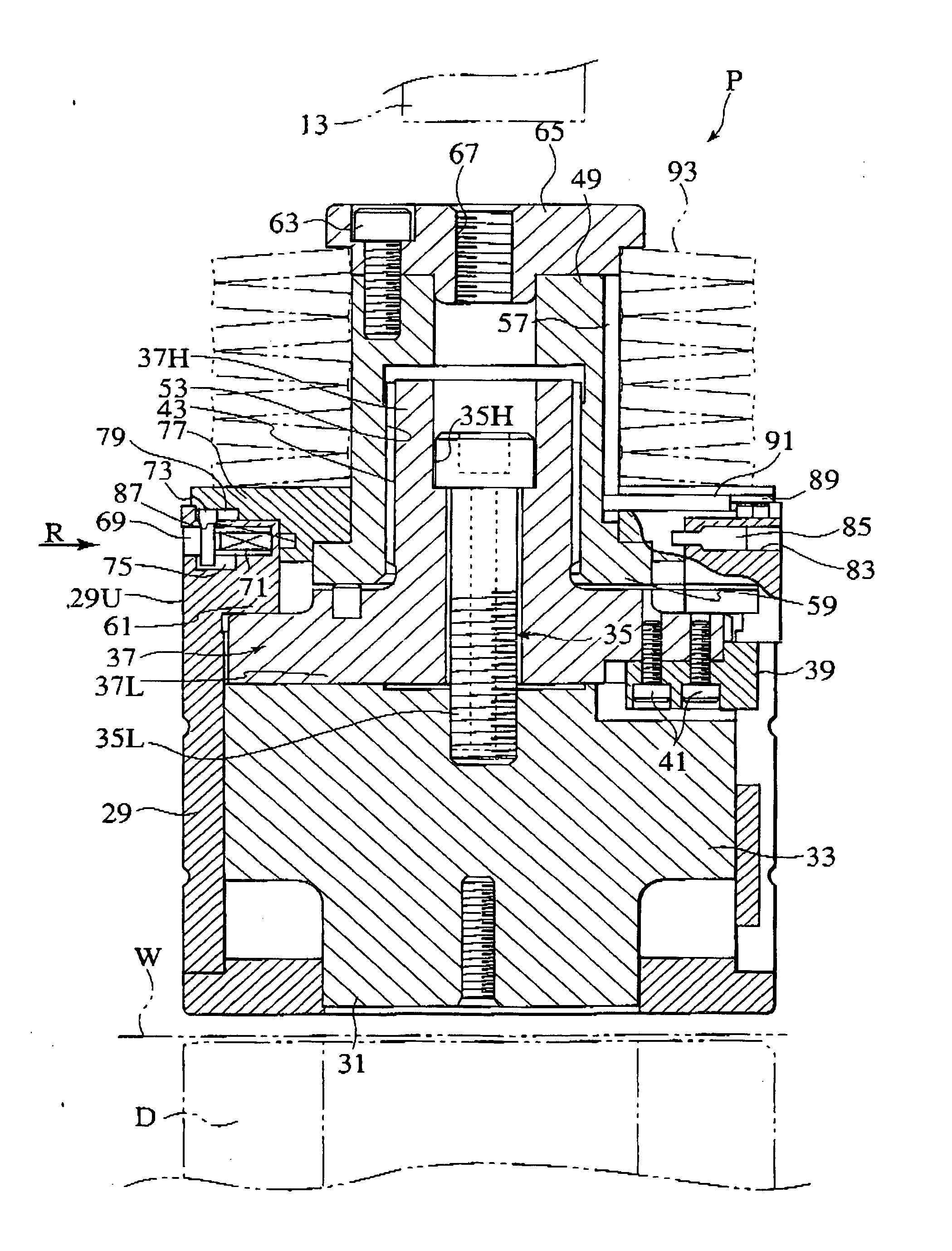
[0040]FIG. 1 is a sectional view showing a punch die P as the die device of the present invention. The punch die P can be mounted to an upper turret such as a turret punch press, and a punch body 33 having a punch blade portion 31 on its lower end is provided into a punch guide 29 so as to be movable up and down, and a lower punch driver 37 is mounted integrally to an upper side of the punch body 33 by a connecting bolt 35 in a normal state.

[0041] Here, a key 39 is mounted to a vicinity of a boundary between the punch body 33 and the lower punch driver 37 by bolts 41, and the punch body 33 and the lower punch driver 37 are supported integrally to the punch guide 29 so as not to rotate and be movable up and down.

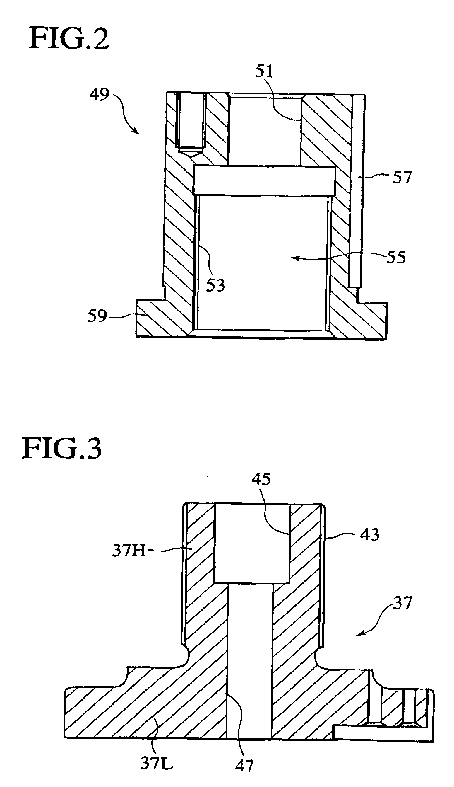
[0042] With reference to FIG. 3, the lower punch driver 37 has a convex portion 37H, which is provided with a thread portion 43 on its outer peripheral surface, on an upper side of a disc-shaped ...

second embodiment

[0069] Next, there will be explained below the die device according to the present invention.

[0070] With reference to FIG. 8, a die device 101 according to the embodiment of the present invention has a cylindrical punch guide 105 which is supported to an upper die holder 103 in a punch press such as a turret punch press (corresponding to an upper turret in the turret punch press) so as to freely move up and down. This punch guide 105 is supported to the upper die holder 103 via a lifter spring (not shown) provided between a flange portion 105F provided on an upper portion of the punch guide 105 and the upper die holder 103 so as to be movable up and down.

[0071] A retainer collar 107 is provided to an upper surface of the punch guide 105 so as to be freely turned and fixed, and a strip elastic means (member) 113 for energizing a punch driver 109 piercing the retainer collar 107 movably only up and down to an upper direction is provided between a punch head 111 mounted to an upper en...


PUM

PropertyMeasurementUnit
energizing forceaaaaaaaaaa
heightaaaaaaaaaa
inner diameteraaaaaaaaaa

Abstract

When a retainer collar 77 is rotated with respect to a punch guide 29 in a turnable manner, an upper punch driver 49 which pierces the retainer collar 77 so as to be movable up and down is rotated with respect to the punch guide 29. As a result, since the upper punch driver 49 is screwed into a lower punch driver 37 and is rotated with respect to the lower punch driver 37 provided on the punch guide 29 movablly up and down, an up-down positional relationship between the upper punch driver 49 and the lower punch driver 37 can be adjusted.

Description

TECHNICAL FIELD [0001] The present invention relates to a die device which is attached to a suitable punch press such a s a turret punch press so as to be used. More specifically, the invention relates to the die device, which is configured to have a punch body with a punch blade portion on its lower end is equipped with a punch guide so as to freely move up and down, and a disc-shaped stripper blade encircling the punch blade portion is detachably provided on a lower end of the punch guide and in which attachment / detachment and fixing of the stripper plate are easy and secure and height adjustment after repolishing of the punch blade portion is easy. BACKGROUND ART [0002] A prior example of the present invention includes Japanese Patent Application Laid-Open No. 10-113725 (1998) (prior example 1) and Japanese Patent Application Laid-Open No. 2000-288656 (prior example 2). [0003] In the prior example 1 (Japanese Patent Application Laid-Open No. 10-113725 (1998)), a punch body having...

Claims


Application Information

Patent Timeline
Patent Type & Authority Applications(United States)
IPC IPC(8): B26F1/14B21D28/12B21D28/34B21D37/14B21D45/00
CPCB21D28/12B21D28/34B21D45/003Y10T83/8732Y10T83/9423Y10T83/9428Y10T83/9476
Inventor IWAMOTO, MASAMIENDO, SHIGERU
Owner AMADA CO LTD
Why Eureka
Try Eureka