Knee bolster

a knee bolster and knee technology, applied in the field of knee bolsters, can solve problems such as restricting lateral sliding movement, and achieve the effects of reducing the chance of leg injuries, reducing the impact of transverse forces, and facilitating transverse load to the kn

Inactive Publication Date: 2006-04-20
STEERING SOLUTIONS IP HLDG +1
View PDF53 Cites 3 Cited by
  • Summary
  • Abstract
  • Description
  • Claims
  • Application Information

AI Technical Summary

Benefits of technology

[0004] A knee bolster constructed according to the present invention is able to better accommodate transverse loads to the knee in a crash event. Should the transverse loads on the knee exceed a predetermined level in a crash event, the knee bolster is able to separate from the vehicle support structure under action of an applied shear force sufficient to break the releasable connection, enabling the knee bolster to slide transversely across the vehicle support structure. The separable, slideable knee bolster of the invention thus has the advantage of reducing transverse forces impacted to the knees under certain crash conditions, thereby reducing the chances of leg injuries.

Problems solved by technology

While this is desirable in may respects, such known deformable knee bolster designs restrict lateral sliding movement of the knees once pocketed.

Method used


Image

  • Knee bolster
  • Knee bolster
  • Knee bolster

Examples


Embodiment Construction

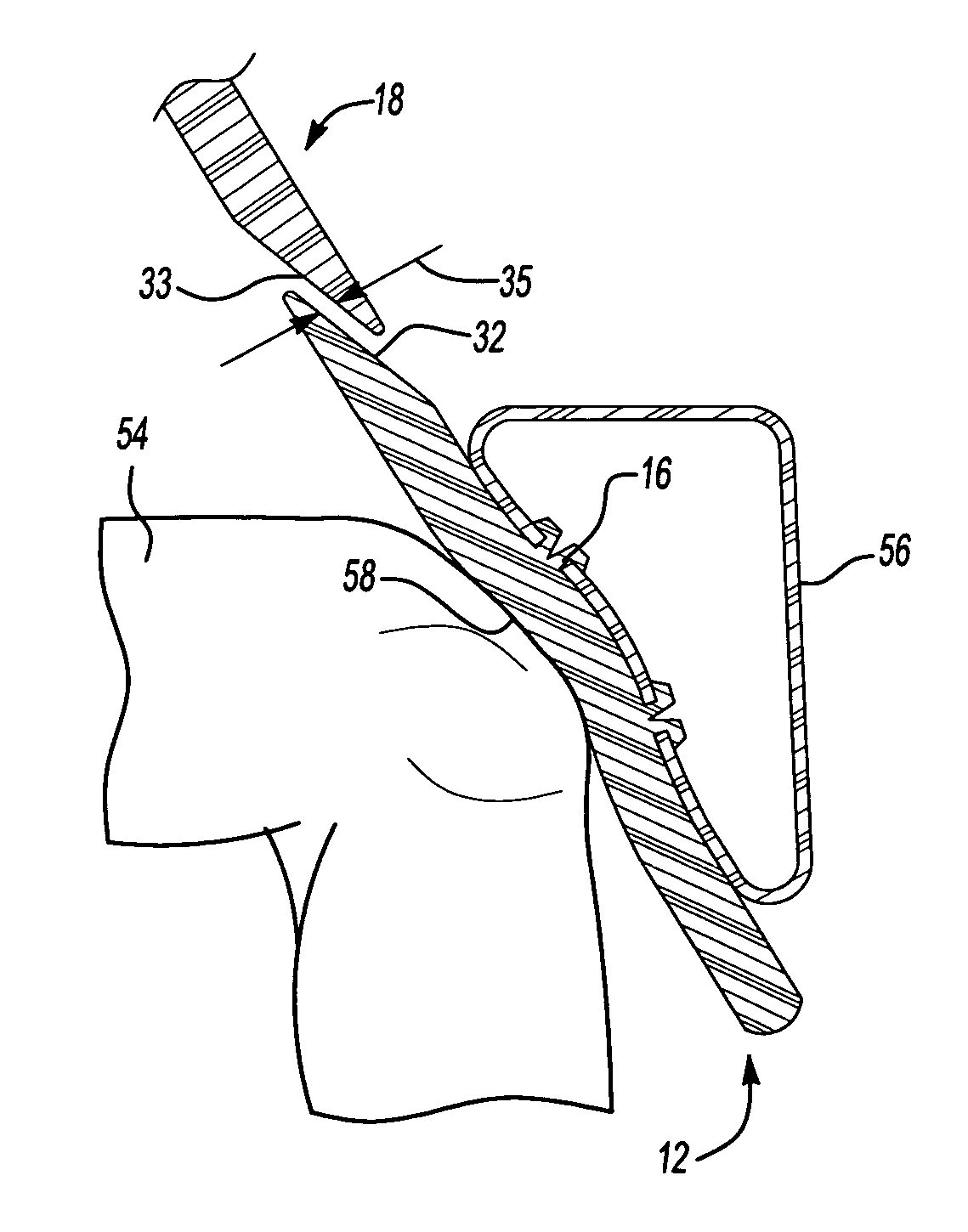
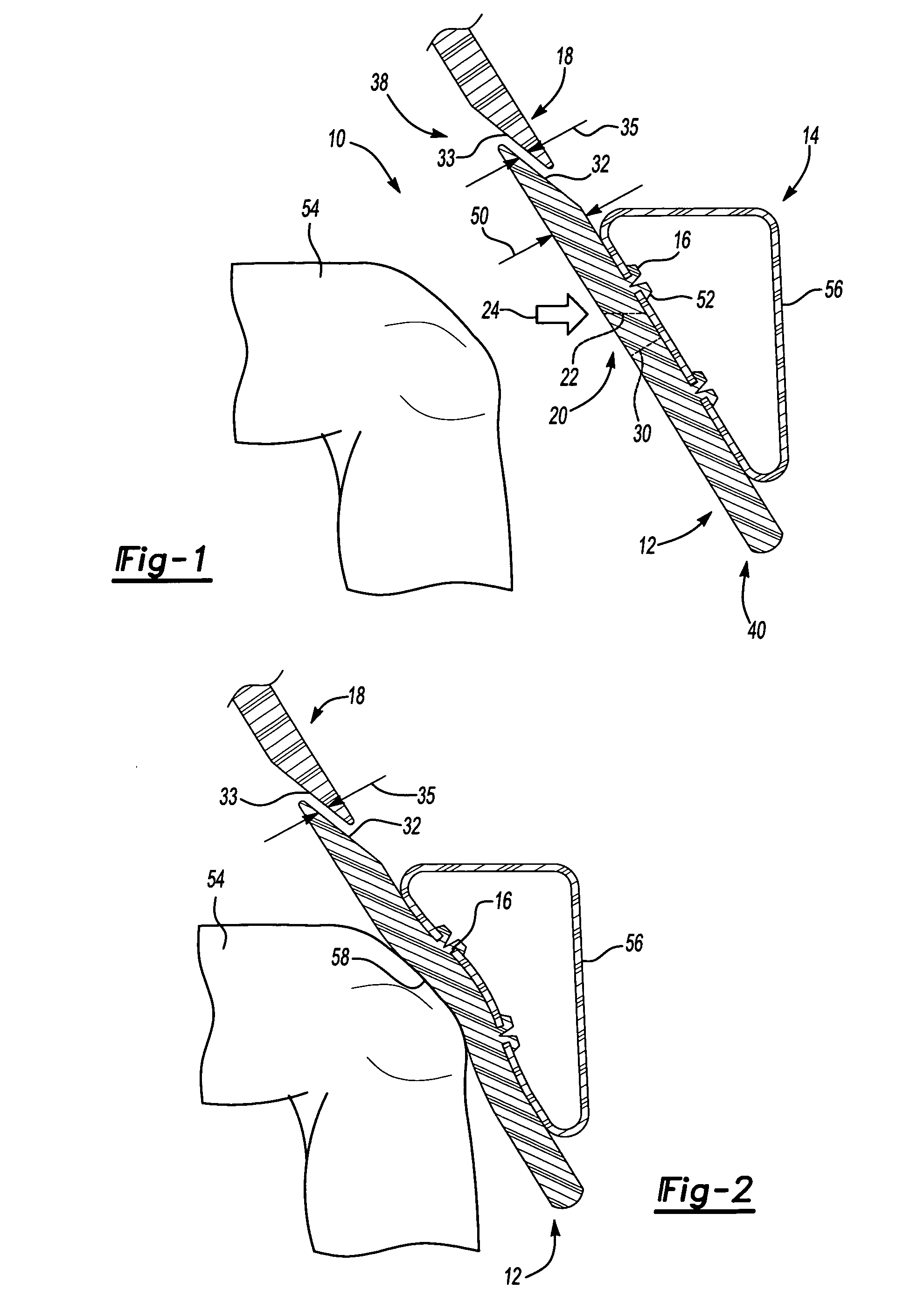
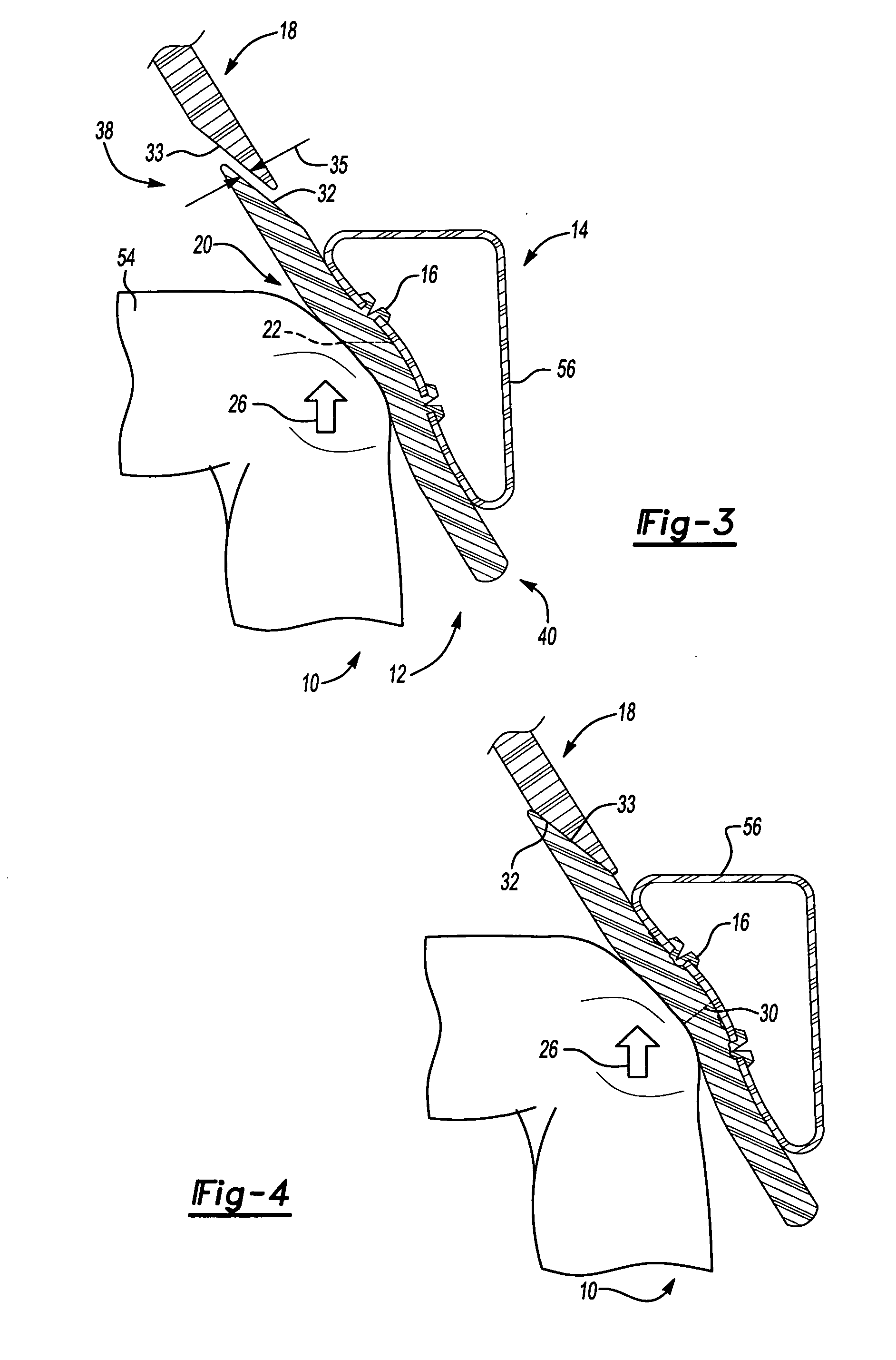
[0015] A plurality of different embodiments of the invention is shown in the Figures of the application. Similar features are shown in the various embodiments of the invention. Similar features have been numbered with a common two-digit reference numeral and have been differentiated by a third digit preceding the two common digits. Similar features are structured similarly, operate similarly, and / or have the same function unless otherwise indicated by the drawings or this specification. Furthermore, particular features of one embodiment can replace corresponding features in another embodiment unless otherwise indicated by the drawings or this specification.

[0016] The invention provides an apparatus and method for absorbing energy in response to a vehicle crash. Referring to a first embodiment of the invention shown in FIGS. 1-8, the apparatus 10 includes a knee bolster 12 disposable in a vehicle for absorbing an impact from at least one knee 54 of a driver. The apparatus 10 also in...


PUM


Abstract

The invention provides an apparatus and method for absorbing energy in response to a vehicle crash. The apparatus includes a knee bolster disposable in a vehicle for absorbing an impact from at least one knee of a driver. The apparatus also includes a connecting device associated with the knee bolster. The connecting device includes a breakable portion for releasibly connecting the knee bolster to the vehicle such that the knee bolster breaks away from the vehicle under predetermined conditions. The method according to the invention includes the step of disposing a knee bolster in a vehicle for absorbing an impact from at least one knee of a driver. The method also includes the step of releasibly connecting the knee bolster to the vehicle such that the knee bolster breaks away from the vehicle under predetermined conditions with a connecting device associated with the knee bolster and having a breakable portion.

Description

FIELD OF THE INVENTION [0001] The invention relates to a knee bolster for absorbing an impact from at least one knee of a driver. BACKGROUND OF THE INVENTION [0002] Most automotive vehicles are equipped with one or more knee bolsters situated below the instrument panel in position to confront the knees of the driver and / or passenger of the vehicle in the event of a crash where the occupant is propelled forward by the momentum of the crash. Some knee bolsters are designed to be deformable on impact and may act to “pocket” the knee. While this is desirable in may respects, such known deformable knee bolster designs restrict lateral sliding movement of the knees once pocketed. SUMMARY OF THE INVENTION AND ADVANTAGES [0003] The invention provides an apparatus and method for absorbing energy in response to a vehicle crash. The apparatus includes a knee bolster disposable in a vehicle for absorbing an impact from at least one knee of a driver. The apparatus also includes a connecting devi...

Claims


Application Information

Patent Timeline
Patent Type & Authority Applications(United States)
IPC IPC(8): B60R21/045
CPCB60R21/045B60R2021/0051
Inventor RIEFE, RICHARD K.COLLIER, BRUCE M.SHAH, MINOO J.PARENTEAU, CHANTAL S.
Owner STEERING SOLUTIONS IP HLDG
Why Eureka
Try Eureka