Adaptive optic lens system and method of use

a technology of optic lens and adaptive lens, applied in the field of ophthalmic lenses, can solve the problems of intractable problems in calculating the proper power, the margin of error of refractive error in biometric systems, etc., and achieve the effect of reducing aberrations

Inactive Publication Date: 2006-04-27
ALCON INC
View PDF89 Cites 43 Cited by
  • Summary
  • Abstract
  • Description
  • Claims
  • Application Information

AI Technical Summary

Problems solved by technology

In another case, posterior chamber phakic IOLs could benefit from post-implant power adjustability since biometry cannot insure proper power selection.
Since the lens can no longer accommodate, the patient typically needs prescription eyeglasses for reading.
In a significant number or cases, after the patient's eye has healed from the cataract surgery, there is a refractive error was beyond the margin of error in the biometric systems.
Thus, there remain intractable problems in calculating the proper power of an IOL for any particular patient.

Method used


Image

  • Adaptive optic lens system and method of use
  • Adaptive optic lens system and method of use
  • Adaptive optic lens system and method of use

Examples


embodiment 190

[0050] Referring to FIG. 9, another IOL embodiment 190 is illustrated in exploded view wherein light energy again is applied only in the non-optic portion 111 instead of the optic portion 110. The embodiment of FIG. 9 comprises simplified adaptive optic that is designed only for spherical corrections and not high order aberration correction. The exemplary IOL of FIG. 9 has an annular SMP member 195 that can be moved from a temporary shape or porosity to a memory shape or porosity to achieve large diopter changes. The central portion or interior phase 196 of the lens can carry a fluid media 140 in an open chamber as described above, for example a silicone of a selected viscosity that may be gel-like. As in previous embodiments, the lens has non-permeable first and second surface layers 124a and 124b that envelope the interior phase 196. As can be seen in FIG. 9, it can be understood that light energy can be scanned and applied to the annular SMP member 195 to move it toward its memor...

embodiment 200

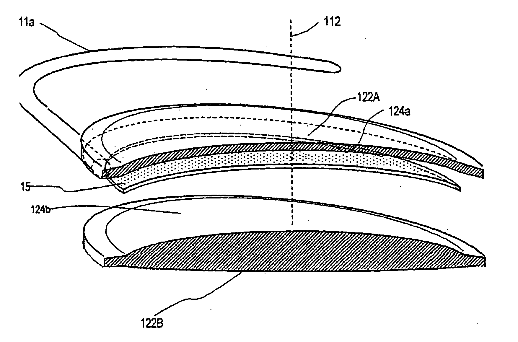
[0052] 2. Type “B” soft adaptive optic system. In another adaptive lens embodiment 200 depicted in FIG. 12, the lens again has an optic portion 210 and a non-optic portion 211. The lens has an interior form or phase 215 as depicted in FIGS. 6A-6C that is enveloped by anterior body portion or surface layer 224a and posterior body portion 224b. In this embodiment, the displacement structures 220 (collectively) operate as described previously to deform an anterior surface layer 224a. This embodiment differs in that shape memory polymers are in the same role to alter the volume of the fluid 225 in the displacement structures 220. In the exemplary embodiment of FIG. 12, the lens carries sacrificial elements 250a-250n in channels 222 (collectively) that individually communicate with space in each individual displacement structures 220a-220n.

[0053] In use, the lens is selected for a patient to have a positive power that exceeds the power indicated by biometry. When the lens 200 is implant...


PUM


Abstract

An lens for correcting human vision, for example an IOL, contact lens or corneal inlay or onlay, that carries and interior phase or layer comprising a pattern of individual transparent adaptive displacement structures. In one embodiment, the displacement structures are actuated by a shape memory polymer (SMP) material or other polymer that is adjustable in shape in response to applied energy. The SUP can be designed to be selectively adjustable in volumetric dimension, modulus of elasticity and / or permeability. The adaptive optic means of the invention can be used to create highly localized surface corrections in the lens to correct higher order aberrations—which types of surfaces cannot be fabricated into and IOL and then implanted. The system of displacement structures also can provide spherical corrections in the lens.

Description

CROSS-REFERENCE TO RELATED APPLICATIONS [0001] This application claims benefit under 35 U.S.C. § 119(e) of Provisional U.S. Patent Application Ser. No. 60 / 402,746 filed Aug. 12, 2002 (Docket No. S-AKO-002) titled Intraocular Lens Implant. This application also is a Continuation-In-Part of U.S. patent application Ser. No. 10 / 360,091 filed Feb. 6, 2002 (Docket No. S-AKO-002) titled Adaptive Optic Lens System and Method of Use. Both of the above applications are incorporated herein by this reference.BACKGROUND OF THE INVENTION [0002] 1. Field of the Invention [0003] The present invention pertains to an ophthalmic lens that allows for post-fabrication correction of higher order aberrations or spherical corrections. More in particular, the invention can be used in IOLs and contact lenses wherein lens components respond to an external energy source, such as a laser, to allow adaptive structures in an interior lens phase to be altered in dimension to thereby adjust or flex the lens shape i...

Claims


Application Information

Patent Timeline
Patent Type & Authority Applications(United States)
IPC IPC(8): G02C7/02A61F2/16G02B27/00G02C7/04
CPCA61F2/145A61F2/16A61F2/1613A61F2/1635A61F2/1637A61F2/1648A61F2210/0014G02B27/0068G02C7/021G02C7/04G02C7/049G02C2202/16G02C2202/22G02C7/041
Inventor SHADDUCK, JOHN H.
Owner ALCON INC
Why Eureka
Try Eureka