Dynamic illumination uniformity and shape control for lithography

Inactive Publication Date: 2006-04-27
NIKON PRECISION
View PDF31 Cites 209 Cited by
  • Summary
  • Abstract
  • Description
  • Claims
  • Application Information

AI Technical Summary

Benefits of technology

[0013] In yet another aspect of the invention, a method for reducing illumination non-uniformity includes illuminating an exposure field with light and measuring brightness of the light throughout the exposure field. The method also inclu

Problems solved by technology

By way of example, in known systems, the projection of light onto a wafer is not always uniform due to illumination drift and other known variations in the optics and projection system of a lithographic tool.
However, such as system may pose long term problems.
For example, this type of optical system (e.g., fly's eye) is ideal for its designed parameters, but cannot compensate for changing characteristics of the system such as, for example, uniformity drift of the illumination intensity over an exposure field over time.
This drift will ultimately reduce the effectiveness and efficacy of the entire lithographic system; that is, the optical system is incapable of adapting to new parameters and

Method used


Image

  • Dynamic illumination uniformity and shape control for lithography
  • Dynamic illumination uniformity and shape control for lithography
  • Dynamic illumination uniformity and shape control for lithography

Examples


Embodiment Construction

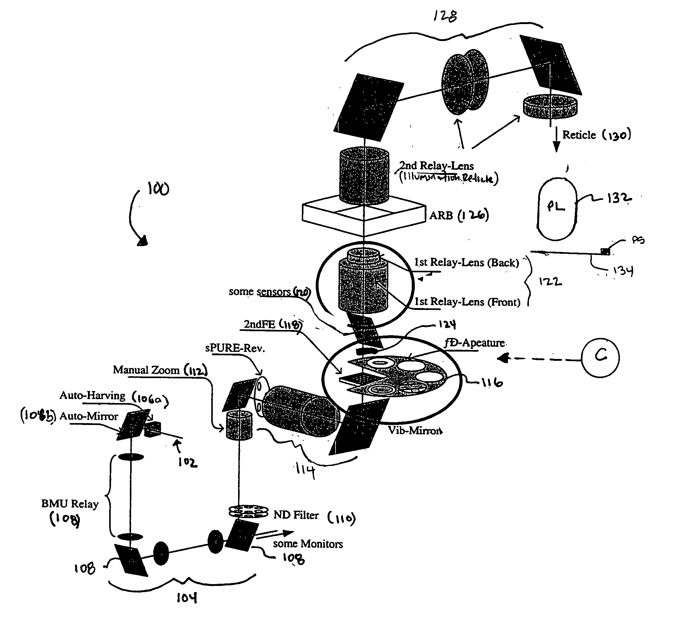
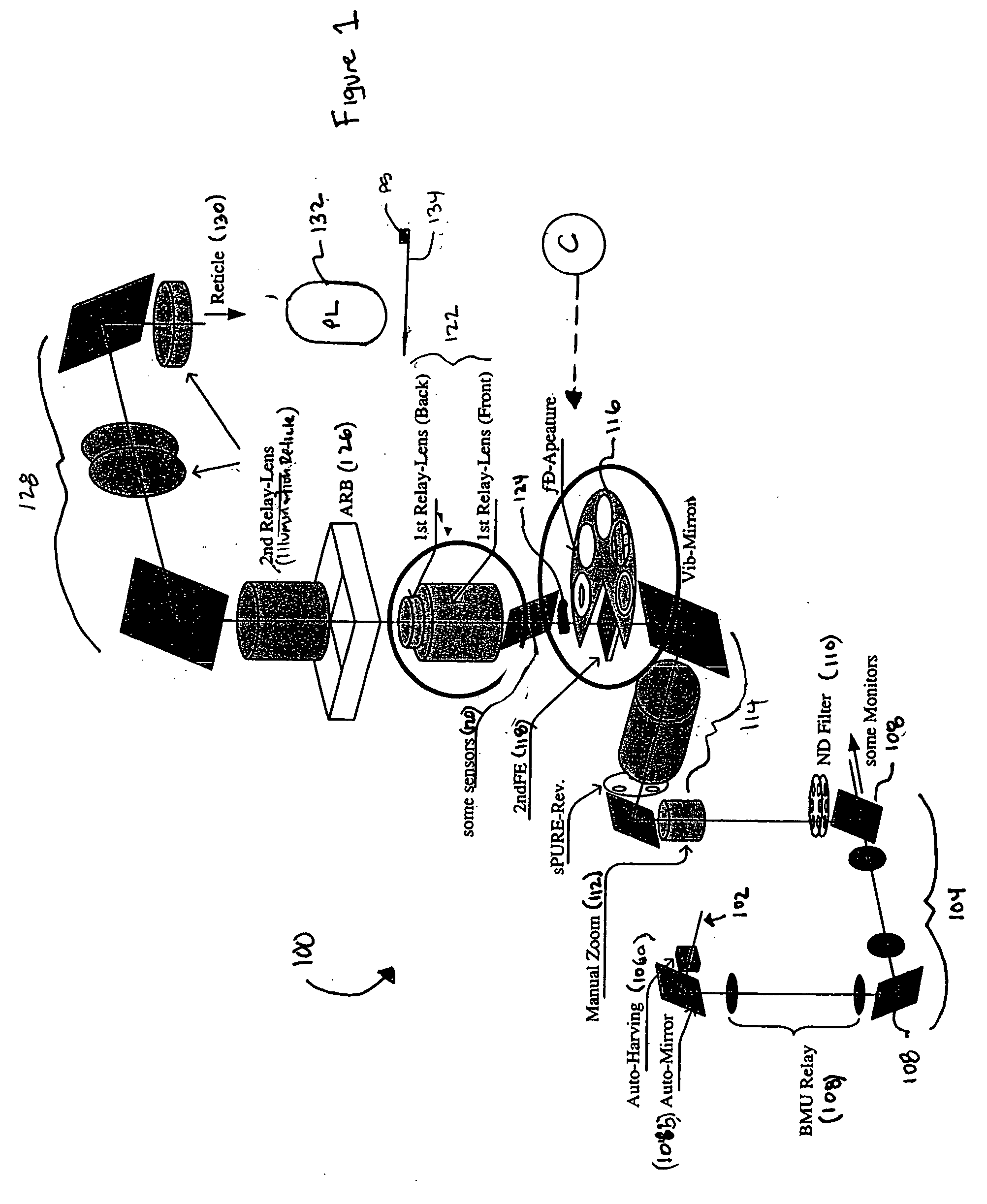
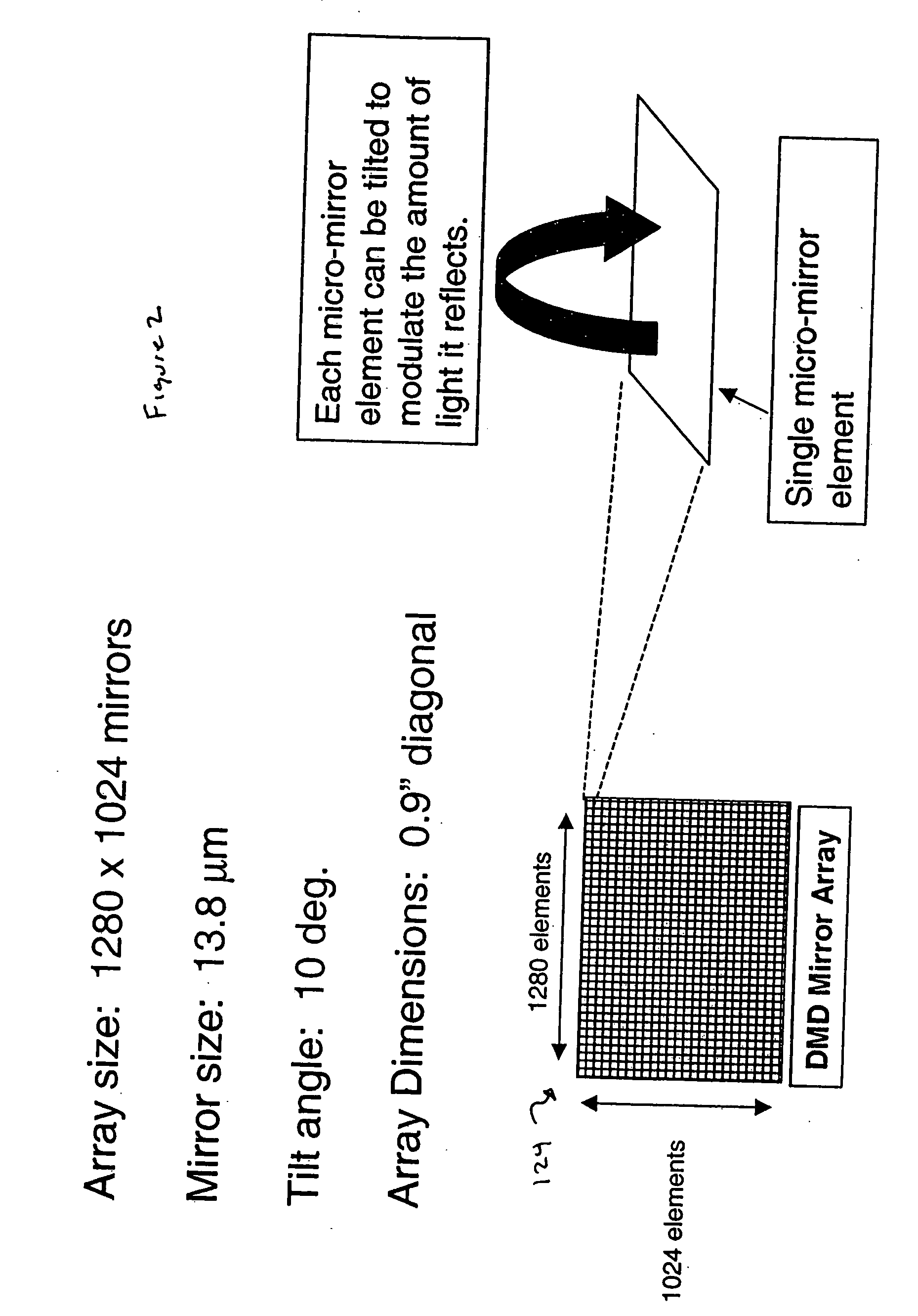
[0027] The invention is directed to, for example, improving an imaging quality across the exposure field using one or more micro-mirror devices. In one embodiment, the system and method allows for a reduction in illumination non-uniformity across the exposure field and dynamic control through the exposure scan. This system and method can thus compensate for a wide variety of illumination non-uniformity signatures across the illumination field as well as dynamic illumination control during the exposure scan, while supporting real-time uniformity feedback control (e.g., continuously adjustable feedback control). In further embodiments, the system of method of the invention functions as a variable aperture with a great degree of flexibility in the definition and use of source shapes for resolution enhancement. This function can eliminate the need for fixed apertures. According, the systems and methods of the invention will greatly increase the efficiency and accuracy of the lithographi...


PUM


Abstract

A subsystem for an exposure apparatus has at least one array of tilting mirrors placed in either an image reticle plane or a conjugate image plane to provide dynamic control of an illumination beam through an exposure field. In the system, an optical subsystem and a plurality of mirrors directs light to a reticle and a sensor senses the illumination distribution of the light at a wafer stage. When the at least one array of tilting mirrors is placed in the image reticle plane, a control is used to interpolate data of the illumination distribution sensed by the sensor, and then control movement of at least one mirror of the array of mirrors based on the interpolated data.

Description

BACKGROUND OF THE INVENTION [0001] 1. Field of the Invention [0002] The invention generally relates to a system and method for providing illumination uniformity and shape control using lithographic tools and, more particularly, to a system and method which dynamically reduces illumination non-uniformity and provides flexibility in shape control across an exposure field using lithographic tools. [0003] 2. Background Description [0004] A lithographic tool uses many components such as, for example, reticles, optical subsystems, apertures and a host of other subsystems to ensure precise image transfer onto a wafer to produce a desired microelectronic device. But, the ability to produce high quality microelectronic devices and reduce yield losses is dependent on the control of the illumination uniformity and shape control of the light being projected from the lithographic tool over an exposure field. That is, (i) illumination uniformity (i.e., brightness) may affect the image quality pro...

Claims


Application Information

Patent Timeline
IPC IPC(8): G03B27/72
CPCG03F7/70116
Inventor BROWN, JAY M.MATSUMOTO, KOICHI
Owner NIKON PRECISION
Why Eureka
Try Eureka