Heat-transfer devices

a technology of heat transfer device and heat transfer device, which is applied in the direction of lighting and heating apparatus, semiconductor/solid-state device details, etc., can solve the problems of insufficient heat conduction through the pwb and/or unenhanced natural convection to keep junction temperatures below the maximum operating limit, the variation of ic stack-up height and parallelism is notable, and the cooling using this general technique is not always easy to achiev

Inactive Publication Date: 2006-04-27
LUCENT TECH INC
View PDF8 Cites 55 Cited by
  • Summary
  • Abstract
  • Description
  • Claims
  • Application Information

AI Technical Summary

Problems solved by technology

Circuit packs and modules typically have one or more printed wire board (PWB)-mounted integrated circuits (ICs) that dissipate enough heat that cooling by simple, un-enhanced natural convection and / or by heat conduction through the PWB is insufficient to keep junction temperatures below maximum operating limits.
Cooling using this general technique, however, is not always easy to achieve.
For instance, variations in IC stack-up height and parallelism present a notable problem.
Given these variations, it is often difficult to achieve a proper, reliable contact between surfaces to maintain a good thermal path.
A problem that may be encountered in making a proper thermal connection between the ICs and the cooling plate is that the distance between the plate and the ICs can vary, both because of IC stack-up height variations and because of thermal expansion of the entire assembly.
Additionally, the two surfaces to be thermally connected may not be sufficiently parallel and in fact may shift relative to one another as the assembly is transported or thermally or mechanically stressed.

Method used


Image

  • Heat-transfer devices
  • Heat-transfer devices
  • Heat-transfer devices

Examples


Embodiment Construction

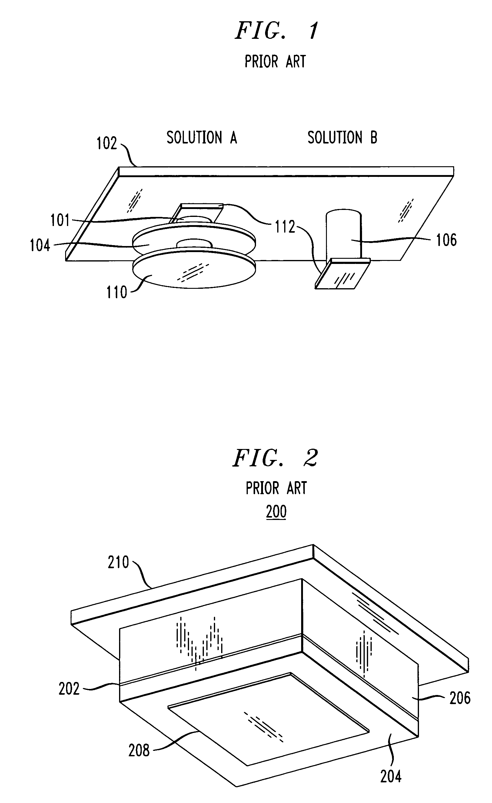
[0033] Prior to describing the embodiments of the present invention, several conventional heat dissipation assemblies will be described with reference to FIG. 1 and FIG. 2. FIG. 1 is a diagram illustrating two conventional heat-transfer device configurations. In a first configuration, labeled “Solution A,” thermal contact between cooling plate 102 and an integrated circuit (IC) (not shown) is made using a heat-transfer structure consisting of aluminum rod 101, e.g., 15 millimeters (mm) in diameter, the length of which bridges most of the gap between the top of the IC and the bottom of cooling plate 102, e.g., a 14.5 mm gap.

[0034] The bottom surface of the aluminum rod is attached, e.g., glued, via socket plate 110 to a top surface of the IC, providing a thermal interface with relatively small thermal resistance. Socket plate 110 may have a diameter of up to about 40 mm (depending on the size of the IC). The variable gap remaining between the top of aluminum rod 101 and the undersid...


PUM


Abstract

Techniques for heat removal are provided. In one illustrative embodiment, a heat-transfer device is provided. The heat-transfer device comprises at least one heat-dissipating structure thermally connectable to at least one heat source, wherein the heat-dissipating structure comprises at least two components thermally coupled to each other and configured to slide relative to one another, one or more of the components comprising one or more heat-dissipating fins configured to dissipate at least a portion of heat from the heat source to air proximate to the device.

Description

CROSS REFERENCE TO RELATED APPLICATIONS [0001] This application is a continuation-in-part of U.S. patent application Ser. No. 10 / 946,571, filed on Sep. 21, 2004.FIELD OF THE INVENTION [0002] This invention relates generally to heat removal from electronic devices and, more specifically, to improved heat-transfer devices for heat removal from electronic devices. BACKGROUND OF INVENTION [0003] Circuit packs and modules typically have one or more printed wire board (PWB)-mounted integrated circuits (ICs) that dissipate enough heat that cooling by simple, un-enhanced natural convection and / or by heat conduction through the PWB is insufficient to keep junction temperatures below maximum operating limits. Generally, passive cooling of these ICs may be obtained by thermally connecting them to heat-dissipating structures, such as heat sinks, which in turn may be cooled by forced air when necessary. [0004] Cooling using this general technique, however, is not always easy to achieve. For inst...

Claims


Application Information

Patent Timeline
Patent Type & Authority Applications(United States)
IPC IPC(8): H05K7/20
CPCF28F3/02F28F13/00H01L23/427H01L23/4338F28F3/048F28F2013/008H01L23/40H01L23/4006H01L2924/0002H01L2924/00F28D15/0241F28D15/0275F28F2275/125
Inventor EWES, INGOHODES, MARC SCOTTKOLODNER, PAUL ROBERT
Owner LUCENT TECH INC
Why Eureka
Try Eureka