Method and device for dividing target image, device for image recognizing process, program and storage media

a target image and image recognition technology, applied in image analysis, image enhancement, instruments, etc., can solve the problems of deteriorating measurement values of feature values obtained from target images, difficulty in dividing target objects into each accurate region of uniform color regions, and increasing processing load

Inactive Publication Date: 2006-04-27
DENSO CORP
View PDF7 Cites 16 Cited by
  • Summary
  • Abstract
  • Description
  • Claims
  • Application Information

AI Technical Summary

Problems solved by technology

However, measured values of feature values, which are obtained from the target image, are deteriorated by various noises that exist in the target image.
Thus, the deteriorated measured values sometimes cause difficulties, such as an inaccurate extraction of a region.
Thus, there is a difficulty in dividing the uniformed color region into each accurate region of target objects.
Thus, there is a problem of increased processing load.
Thus, there is difficulty in directly incorporating each set of sensor output information into a pixel of the image.

Method used


Image

  • Method and device for dividing target image, device for image recognizing process, program and storage media
  • Method and device for dividing target image, device for image recognizing process, program and storage media
  • Method and device for dividing target image, device for image recognizing process, program and storage media

Examples


first embodiment

[0035] A first embodiment of the present invention will be described with reference to the accompanying drawings.

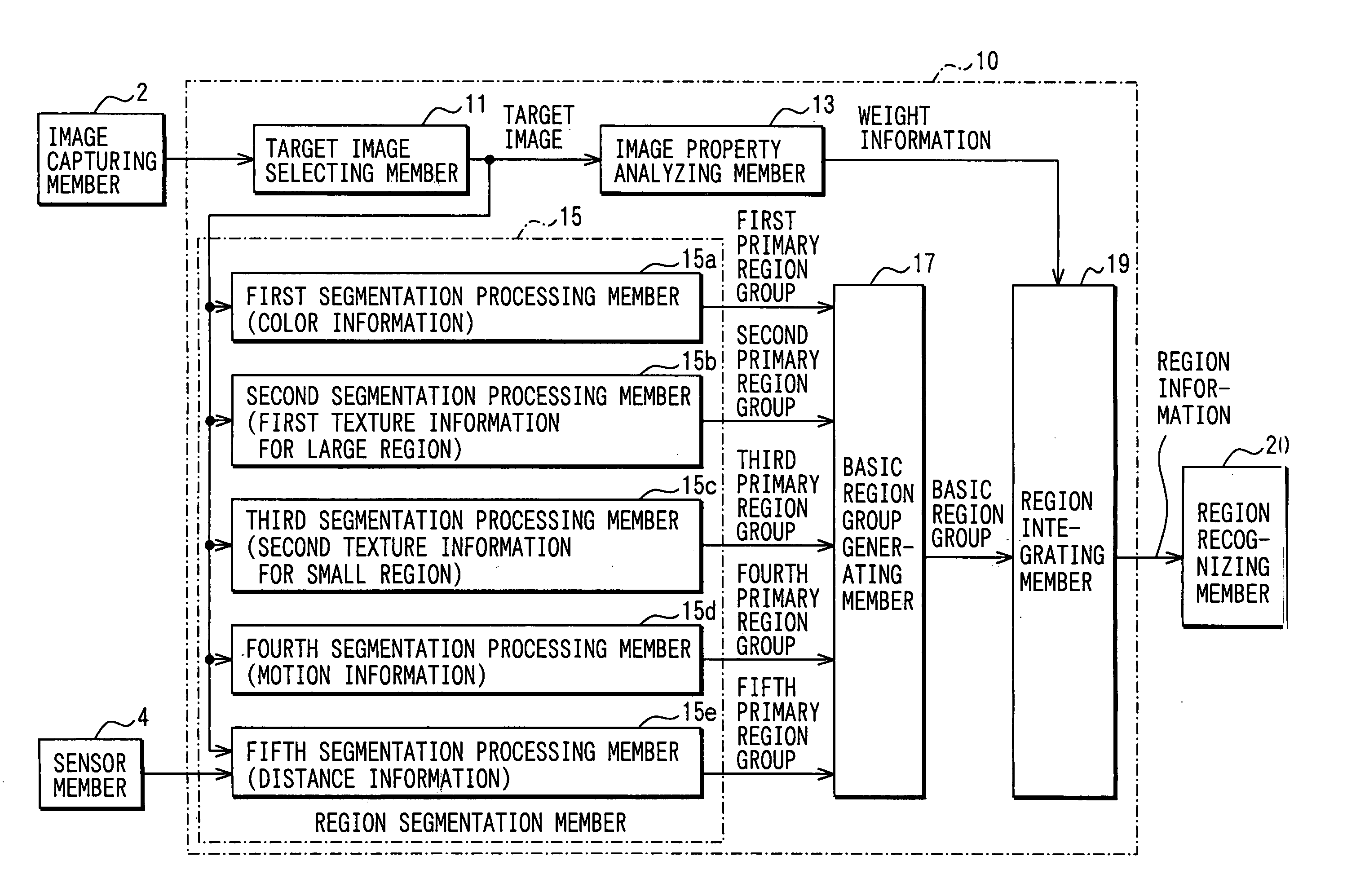
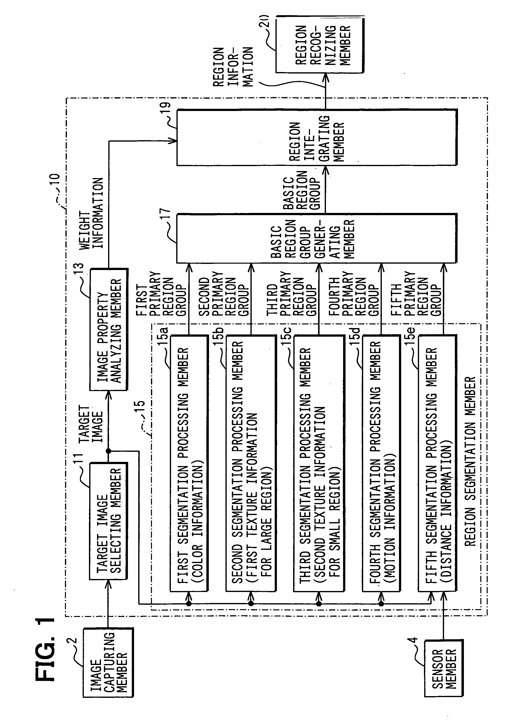
[0036]FIG. 1 is a block diagram of a general structure of an image recognizing process device of the present embodiment.

[0037] The image recognizing process device includes an image capturing member 2, a sensor member 4, a region extracting member 10 and a region recognizing member 20. The sensor member 4, which includes a laser radar, measures a distance to each target object existing in a detecting region, which is the same region as a captured region of the image capturing member 2. The region extracting member 10 receives input images from the image capturing member 2 and detected data from the sensor member 4, and divides the input images into a plurality of regions. Then, the region extracting member 10 extracts a recognizing target region from the plurality of regions. The region recognizing member 20 recognizes the target object, which is described by the recogn...

second embodiment

[0087] A second embodiment will be described.

[0088] In the present embodiment, contents of only the basic region group generating process are different from the first embodiment. Thus, the basic region group generating process will be described mainly.

[0089] In the present embodiment, at S510, as shown in FIG. 11, the basic region group generating process starts with overlapping a part or a whole of the first to fifth primary region groups to generate the basic region group.

[0090] Specifically, as shown in FIG. 12, in a case, where primary region groups are overlapped, the target image is divided into delimited regions, which is delimited by corresponding boundaries of each primary region. And all the delimited regions are defined as basic regions, which compose the basic region group.

[0091]FIG. 12 shows a case, where the first, the third and the fifth primary region group are overlapped.

[0092] At S520, one of the basic regions, which are generated by an above-described method,...


PUM


Abstract

According to a region dividing device, a region dividing member generates a plurality of primary region groups, each of which includes a plurality of primary regions. Each of the plurality of primary regions is characterized by each measured value of feature values. A basic region group generating member generates a single basic region group that includes a plurality of basic regions produced by dividing the target image. Each basic region is characterized by each measured value of feature values. Each measured value is obtained based on the measured values of the plurality of primary regions of the plurality of primary region groups. A region integrating member integrates similar adjacent basic regions into a corresponding integrated region, based on a weighted Euclidean distance between the similar adjacent basic regions.

Description

CROSS REFERENCE TO RELATED APPLICATION [0001] This application is based on and incorporates herein by reference Japanese Patent Application No. 2004-312331 filed on Oct. 27, 2004. BACKGROUND OF THE INVENTION [0002] 1. Field of the Invention [0003] The present invention relates to a region dividing (or segmenting) method and device for extracting a region, which is a recognizing target in the image, and relates to an image recognizing process device, which is equipped with the region dividing device. [0004] 2. Description of Related Art [0005] Conventionally, a region dividing process has been performed so as to serve as an art for extracting such recognizing targets, as “sky”, “ground”, “forest” and “human beings”, in an image. [0006] An accuracy of a region, which is extracted by the region dividing process, has a considerable influence on results of a code processing and a recognizing / extracting processing in later processes. Therefore, the accuracy of the region dividing process ...

Claims


Application Information

Patent Timeline
Patent Type & Authority Applications(United States)
IPC IPC(8): G06K9/34
CPCG06T7/0081G06T7/402G06T2207/10016G06T2207/20021G06T2207/20048G06T7/11G06T7/42
Inventor ENOMOTO, MITSUHIRO
Owner DENSO CORP
Why Eureka
Try Eureka