Internal fixation system for spine surgery

a spine surgery and fixation system technology, applied in the field of internal fixation system, can solve the problems of difficult installation of the present system through very small portals or working channels

Inactive Publication Date: 2006-04-27
CONCEPT MATRIX
View PDF10 Cites 78 Cited by
  • Summary
  • Abstract
  • Description
  • Claims
  • Application Information

AI Technical Summary

Problems solved by technology

The presently available systems are difficult to install through very small portals or working channels, e.g., a working channel less than one inch in diameter.

Method used


Image

  • Internal fixation system for spine surgery
  • Internal fixation system for spine surgery
  • Internal fixation system for spine surgery

Examples


Embodiment Construction

[0041] Certain terminology is used in the following description for convenience only and is not limiting. The words “right”, “left”, “lower”, and “upper” designate directions in the drawing to which reference is made. The words “inwardly” and “outwardly” refer direction toward and away from, respectively, the geometric center of the object described and designated parts thereof. The terminology includes the words above specifically mentioned, derivatives thereof and words of similar import. Additionally, the word “a”, as used in the claims and in the corresponding portions of the specification, means “at least one.”

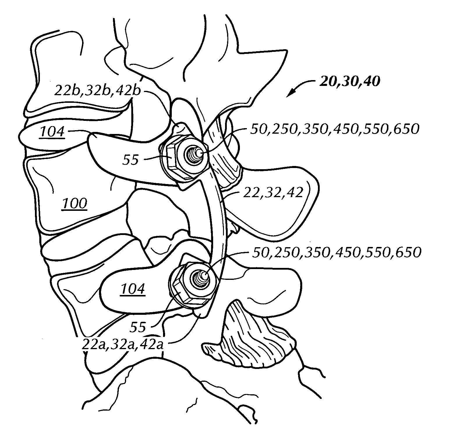
[0042] Referring to the drawings in detail, wherein like reference numerals indicate like elements throughout, FIG. 2 shows an internal fixation rod 22 for minimally invasive and open spine surgery in accordance with a first preferred embodiment of the present invention. The fixation rod 22 is an internally-mounted device, with respect to a patient, for fixing two or more...


PUM


Abstract

An internal fixation rod for spine surgery includes an elongate body, a first rod end, a second rod end, a first mounting member and a second mounting member. The first mounting member is disposed proximate the first rod end, and the second mounting member is disposed proximate the second rod end. The first mounting member and the second mounting member are smaller in cross-section than the elongate body.

Description

CROSS REFERENCE TO RELATED APPLICATIONS [0001] This application claims priority to U.S. Provisional Patent Application No. 60 / 622,174 filed on Oct. 26, 2004, entitled “Internal Fixation System.”BACKGROUND OF THE INVENTION [0002] The present invention relates to an apparatus and method for performing spine surgery and more particularly to an internal fixation system for minimally invasive and open spine surgery and a method for using the internal fixation system for spine surgery. [0003] Referring to prior art FIGS. 1A and 1B, the spine 120, also known as the vertebral column or the spinal column, is a flexible column of vertebrae 100 (special types of bones) held together by muscles, ligaments and tendons. The spine 120 extends from the cranium (not shown) to the coccyx 126, encasing a spinal cord 128 and forming the supporting axis of the body (not shown). The spinal cord 128 is a thick bundle of nerve tissue (nerves) that branch off to various areas of the body for the purposes of...

Claims


Application Information

Patent Timeline
Patent Type & Authority Applications(United States)
IPC IPC(8): A61F2/30
CPCA61B17/3468A61B17/7001A61B17/7007A61B17/7011A61B2017/867
Inventor ECKMAN, WALTER W.
Owner CONCEPT MATRIX
Why Eureka
Try Eureka