

USB control circuit for saving power and the method thereof
- Summary
- Abstract
- Description
- Claims
- Application Information
AI Technical Summary
Benefits of technology
Problems solved by technology
Method used
Image

Examples
Embodiment Construction
[0022] Some embodiments of the invention will now be described in greater detail. However, it should be noted that the present invention can be practiced in a wide range of other embodiments besides those explicitly described, and the scope of the present invention is expressly not limited except as specified in the accompanying claims. Moreover, some irrelevant details are not drawn in order to make the illustrations concise and to provide a clear description for easily understanding the present invention.
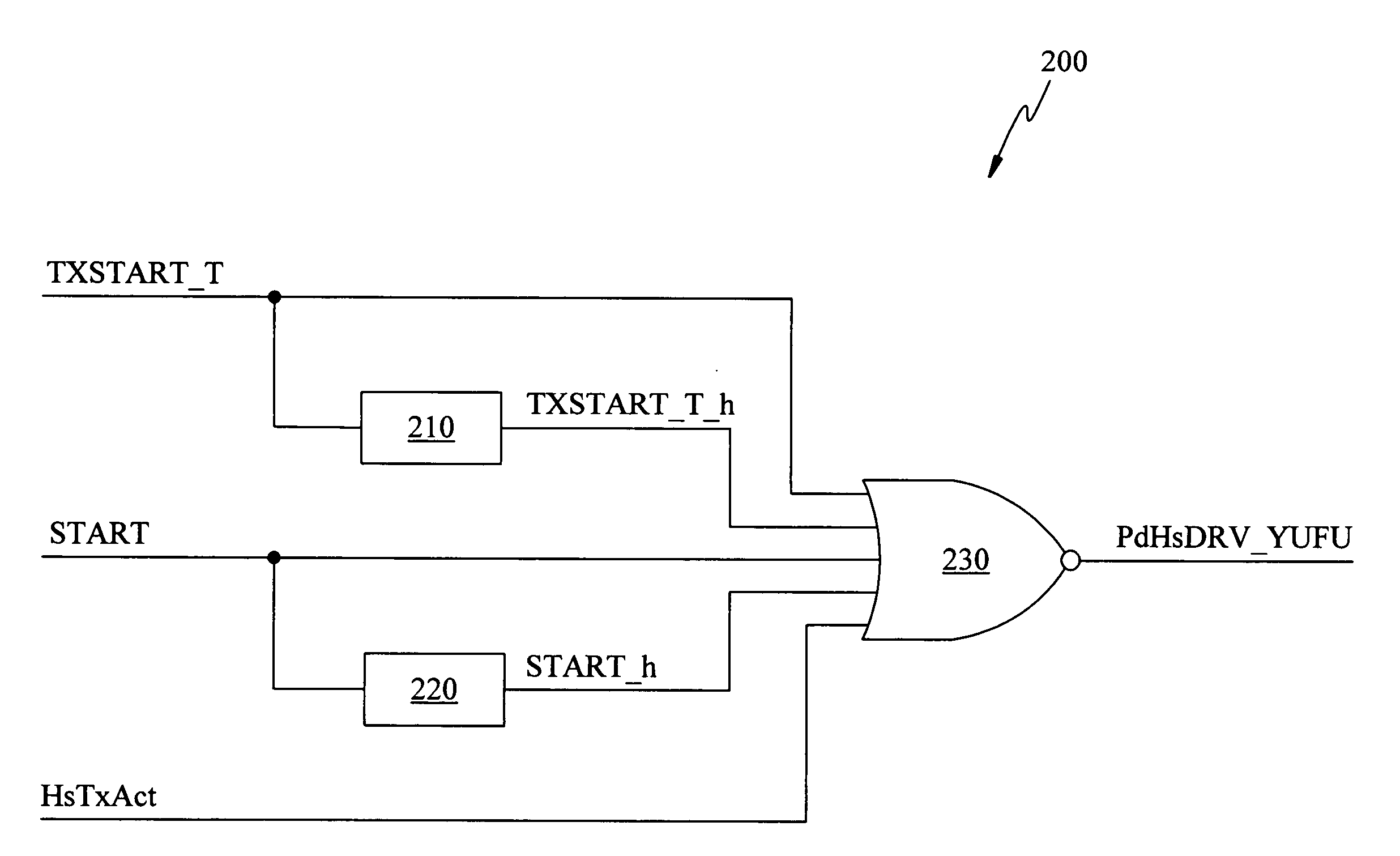
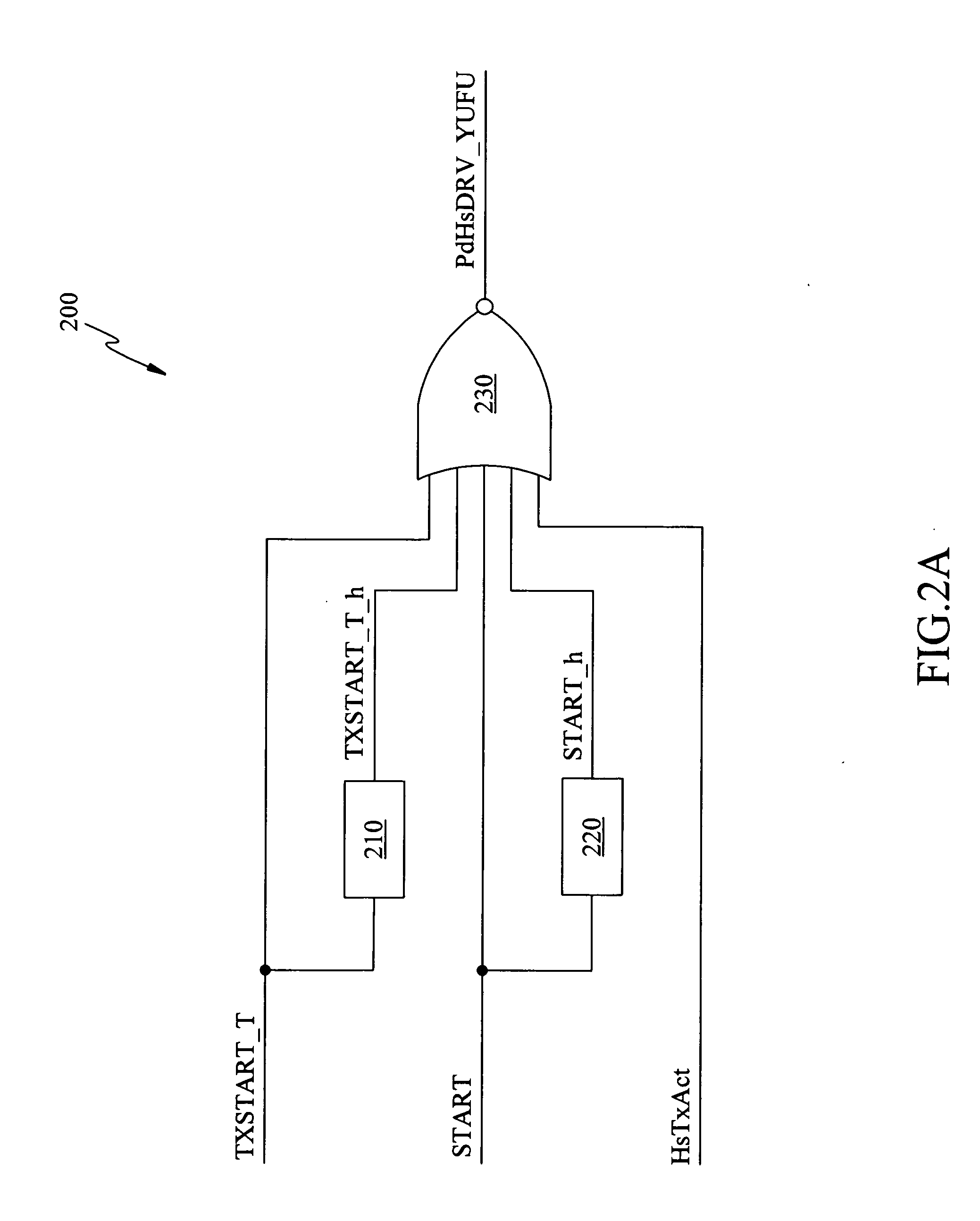
[0023] Referring to FIG. 2A, a preferred embodiment for generating a control signal in accordance with the present invention is illustrated. A first logic circuit 200 receives a first signal TXSTART_T, a second signal START, and a third signal HsTxAct, and generates a control signal PdHsDRV_YUFU. Wherein, the control signal PdHsDRV_YUFU is utilized to indicate whether to activate the transmitting module in a USB device (not shown), the third signal HsTxAct is utilized to indicate...
PUM
 Abstract
Description
Claims
Application Information