Stackable rolling rack apparatus

Inactive Publication Date: 2006-05-04
SUMMER MFG
View PDF10 Cites 67 Cited by
  • Summary
  • Abstract
  • Description
  • Claims
  • Application Information

AI Technical Summary

Benefits of technology

[0015] Typically, to ship numbers of its pipe rack products the mobile pipe rack apparatus are stacked and are typically encapsulated in a plastic sheath or are otherwise secured in stacked or nested relation. For stacking, the wheels or casters are typically removed. They can easily become lose or damaged when removed from the pipe rack cart.
[0016] The present invention of the rolling rack apparatus includes the following features that promote stacking or nesting of the rack apparatus while eliminating the need for disassembly of components and the potential for lost components. The upright members are pivotally mounted to the base unit to enable pivotal movement from an upright position to a lowered position for stacking. In the upright position, the upright members are preferably locked by spring-loaded pins. In the lowered position, the upright members are efficiently secured. The upper ends of the four corner uprights are r

Problems solved by technology

They can easily become lose or damaged

Method used


Image

  • Stackable rolling rack apparatus
  • Stackable rolling rack apparatus
  • Stackable rolling rack apparatus

Examples


first embodiment

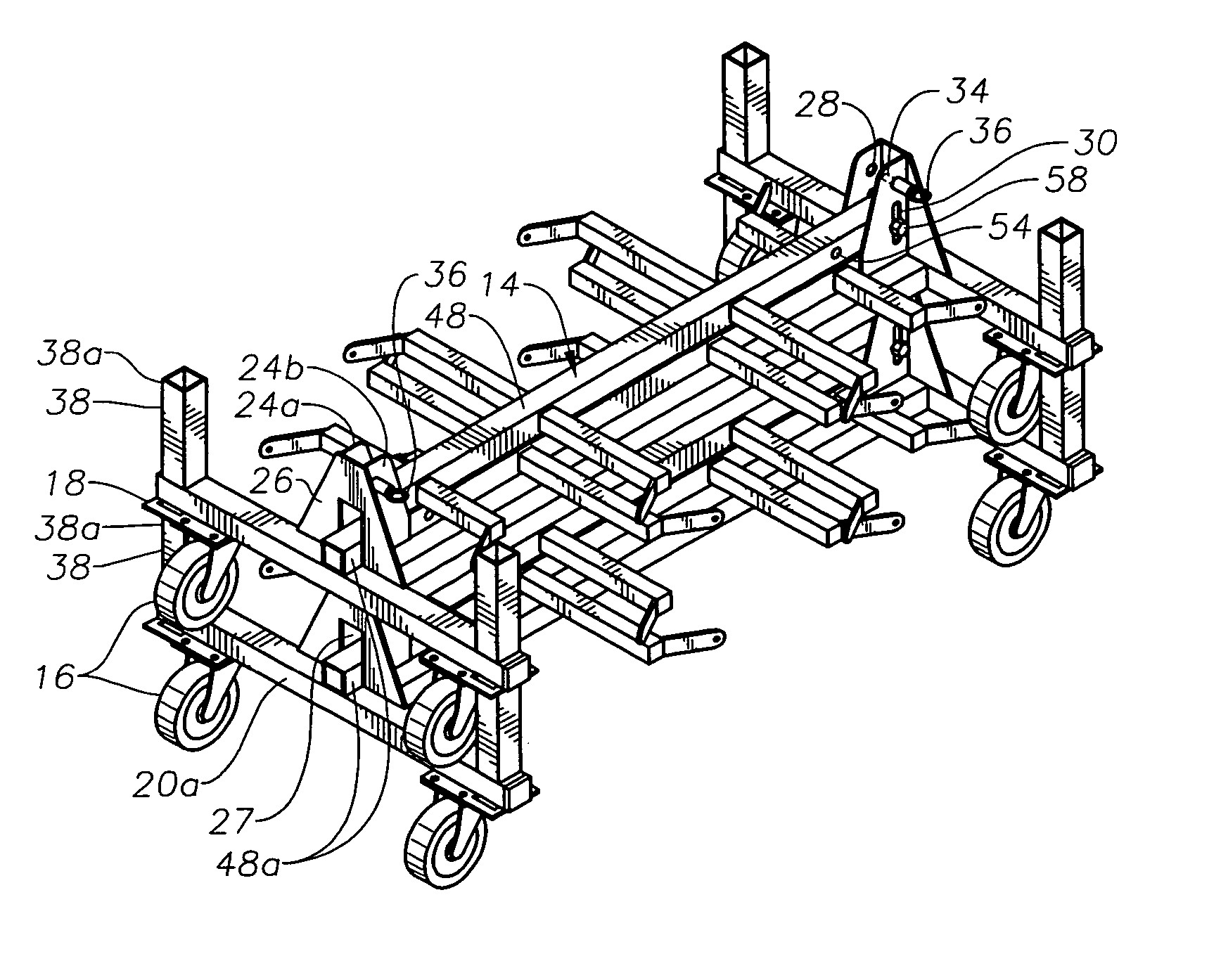
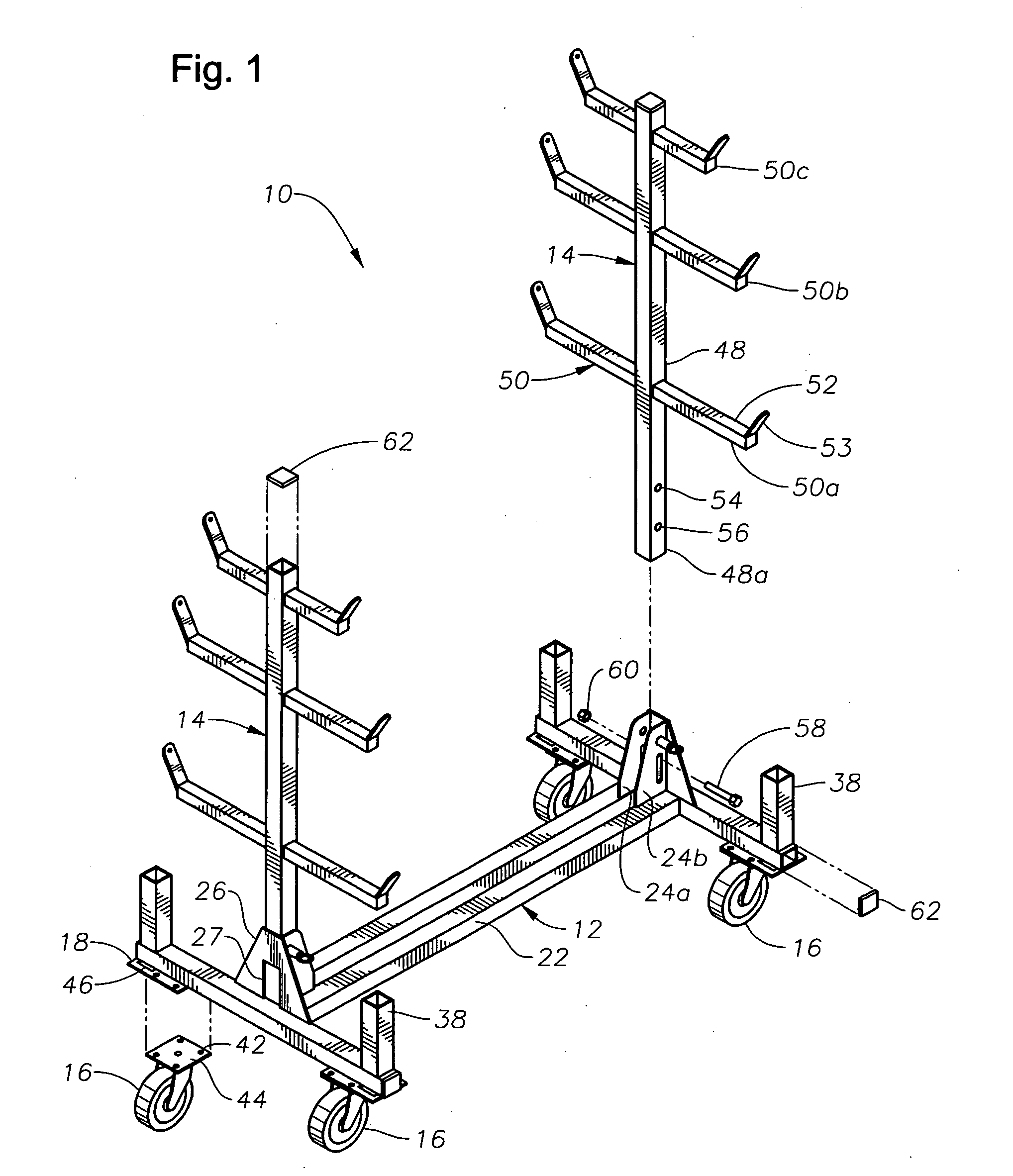
[0031] The stackable rolling rack apparatus according to the present invention, generally designated as numeral 10, is shown in FIGS. 1-4. The rack apparatus 10 includes a base unit 12 having a pair of upright support assemblies 14 attached to the base unit 12. Preferably, four wheels, more preferably casters 16, are mounted to caster mounts 18 attached to the base unit 12. Preferably, at least two of the four casters 16 are swivel-mount casters.

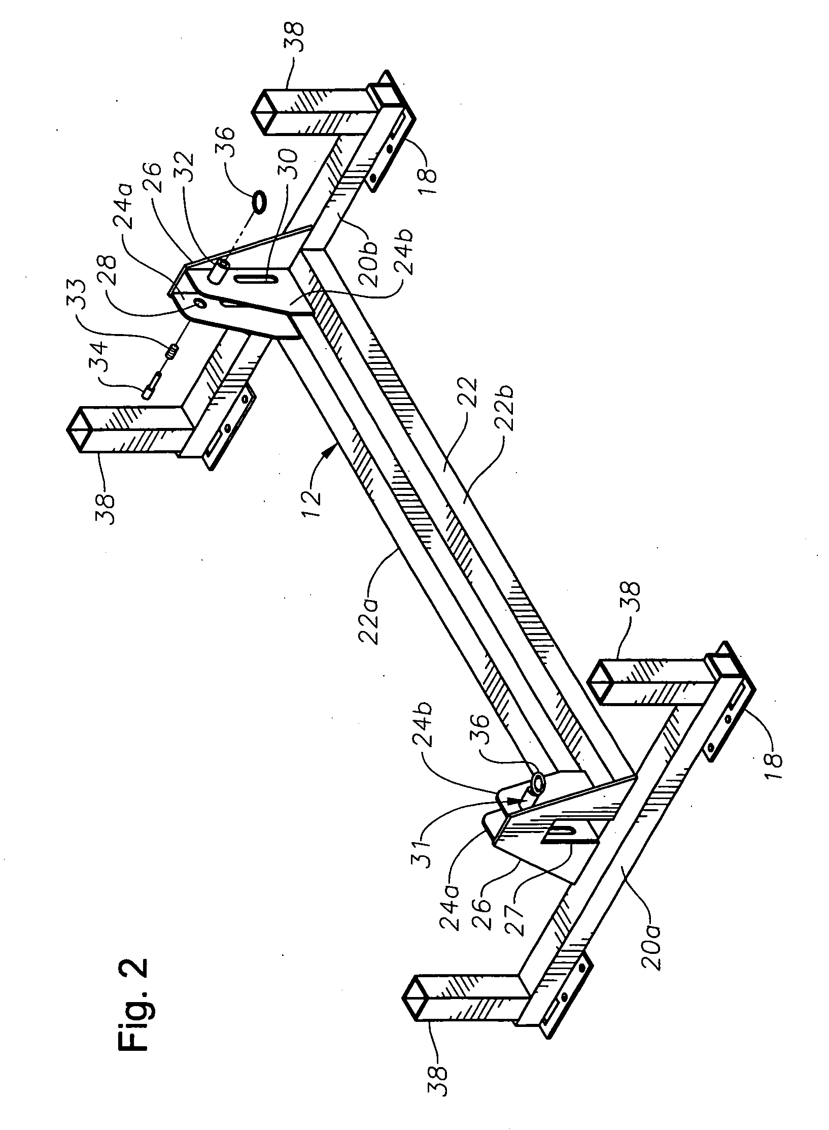
[0032] As shown in FIG. 2, the base unit 12 includes a pair of transverse end members 20a and 20b transversely oriented relative to center rail 22, preferably a pair of center rails 22a and 22b. The end members 20a and 20b are preferably attached to the ends of the pair of center rails 22a and 22b. Preferably, the center rails 22a and 22b are parallel with each other and have a gap between them. At each end of the pair of center rails 22a, 22b, there is a pair of upright mounting plates 24a and 24b, and a transverse support plate 26. Each up...

fourth embodiment

[0049]FIGS. 7 and 8 show the rolling rack apparatus, generally designated 100. The rack apparatus 100 includes a base unit 112 and preferably four wheels or casters 16 mounted to caster mounts 18 attached to the base unit 112. As shown in FIG. 8, the base unit 112 includes a pair of transverse end members 120a and 120b transversely oriented relative to a center rail 22, preferably a pair of center rails 22a and 22b. The end members 120a and 120b are preferably attached to the ends of the pair of center rails 22a and 22b. Preferably, the center rails 22a and 22b are parallel with each other and have a gap between them. The base unit 112 preferably includes a pair of base side rails 121a and 121b spanning between and connected to the ends of the transverse end members 120a and 120b. The pair of base side rails 121a and 121b provide additional structural rigidity and integrity to the base unit 112. In the preferred embodiment, the side rails 121a, 121b are made from structural angle me...

fifth embodiment

[0057]FIGS. 10 and 11 show the rolling rack apparatus, generally designated 200. The rack apparatus 200 includes a base unit 212 and preferably four wheels or casters 16 mounted to caster mounts 18 attached to the base unit 212. As shown in FIG. 11, the base unit 212 includes a pair of transverse end members 220a and 220b transversely oriented relative to a center rail 22, preferably a pair of center rails 22a and 22b. The end members 220a and 220b are preferably attached to the ends of the pair of center rails 22a and 22b. The base unit 212 preferably includes a pair of base side rails 221a and 221b spanning between and connected to the ends of the transverse end members 220a and 220b. The pair of base side rails 221a and 221b provide additional structural rigidity and integrity to the base unit 212. Preferably, a screen 264 or plate is attached to the base unit 212. As shown in FIG. 11, the screen 264 is preferably attached to the lower surface of the rails 221a, 22a, 22b and 221b...


PUM


Abstract

A stackable rolling rack apparatus capable of being stacked on a similar rolling rack apparatus includes a base unit having a generally horizontal frame assembly and a plurality of upright side members. Wheels are mounted to the base unit and extend below the lower surface of the frame assembly. Mounting plates are attached to the base unit such that upon stacking each mounting plate cooperatively engages an upright side member of the lower similar rolling rack apparatus. The apparatus includes support assemblies pivotally connected to the base unit. Each support assembly has an upright position and a lowered position. In the upright position each support assembly extends vertically above an upper end portion of the upright side members, and in the lowered position each support assembly is lower than the upper end portion of the upright side members.

Description

CROSS-REFERENCE TO RELATED APPLICATIONS [0001] This application claims the benefit of U.S. Provisional Patent Application Ser. No. 60 / 623,029, filed Oct. 28, 2004.BACKGROUND OF THE INVENTION [0002] 1. Field of the Invention [0003] The invention relates to portable rolling rack apparatus for supporting various items, as for example a number of pipes, and more particularly relates to portable rolling rack apparatus having upright supports members for supporting various items with the rolling rack apparatus being stackable for ease of storage or shipping. [0004] 2. Description of the Related Art [0005] There are many prior art rolling dollies, carriages and rack apparatus in existence which are used for a variety of purposes. There are many instances, such as for storage or shipping, in which it is desirable to be able to stack the rolling dollies, carriages and rack apparatus. Following are some prior art patents disclosing a variety of portable wheeled units having a stacking feature...

Claims


Application Information

Patent Timeline
IPC IPC(8): A47B43/00
CPCB62B3/002B62B3/022B62B3/10B62B3/16B62B2205/006B62B2205/20B62B3/102B62B3/02
Inventor VELEZ, LAWRENCECOLLINS, ROBERT H. JR.
Owner SUMMER MFG
Why Eureka
Try Eureka