Meter ring locking device

a technology of locking device and meter ring, which is applied in the direction of locking device, liquid/fluent solid measurement, instruments, etc., can solve the problems of utility companies' difficulty in controlling the key, cost and cumbersome, lost or become inoperative, etc., and achieves substantial cost savings and minimizes the extent of key control.

Inactive Publication Date: 2006-12-14
DEBRODY ROBERT F +2
View PDF19 Cites 5 Cited by
  • Summary
  • Abstract
  • Description
  • Claims
  • Application Information

AI Technical Summary

Benefits of technology

[0018] In accordance with an embodiment of the present invention, the latch does not need a key to lock, locks automatically upon clamping the ring to the utility meter and does not separate from the housing in the unlock state of the blade, avoiding the problems with the prior art ring clamping devices. One problem avoided is where a key is required for installation of each clamping ring, requiring numerous keys and their attendant tight control. A further problem is avoided where the separated plungers may become lost or damaged, such as when dropped or otherwise mishandled, and require replacement plungers to be carried by service technicians, not necessary with the various embodiments of the present invention. With the embodiments of the present invention, the service technician need not carry a key to install the clamping ring minimizing the extent to implement key control for numerous keys no longer necessary. Installation of meter clamping rings is widespread as compared to merely servicing an occasional meter for repair, which requires a key for opening the meter. In addition, non-utility company workers such as electricians can install the clamping rings according to embodiments of the present invention, since no key is required. This results in substantial cost savings.

Problems solved by technology

Control of the keys presents a problem to the utility companies.
Since such keys can open the clamping ring, tight control of such keys requires a tracking system to keep track of all keys in use at all times. This can be costly and cumbersome.
Also, the plunger locks generally are separate devices and sometimes can be lost or become inoperative.
This can create a further problem with respect to locating or carrying spare plunger locks, which is also costly and cumbersome to utility companies which have hundreds, if not thousands, of such meters which require service.
This creates a problem if the operator overlooks pushing the lock into locking position.

Method used


Image

  • Meter ring locking device
  • Meter ring locking device
  • Meter ring locking device

Examples


Embodiment Construction

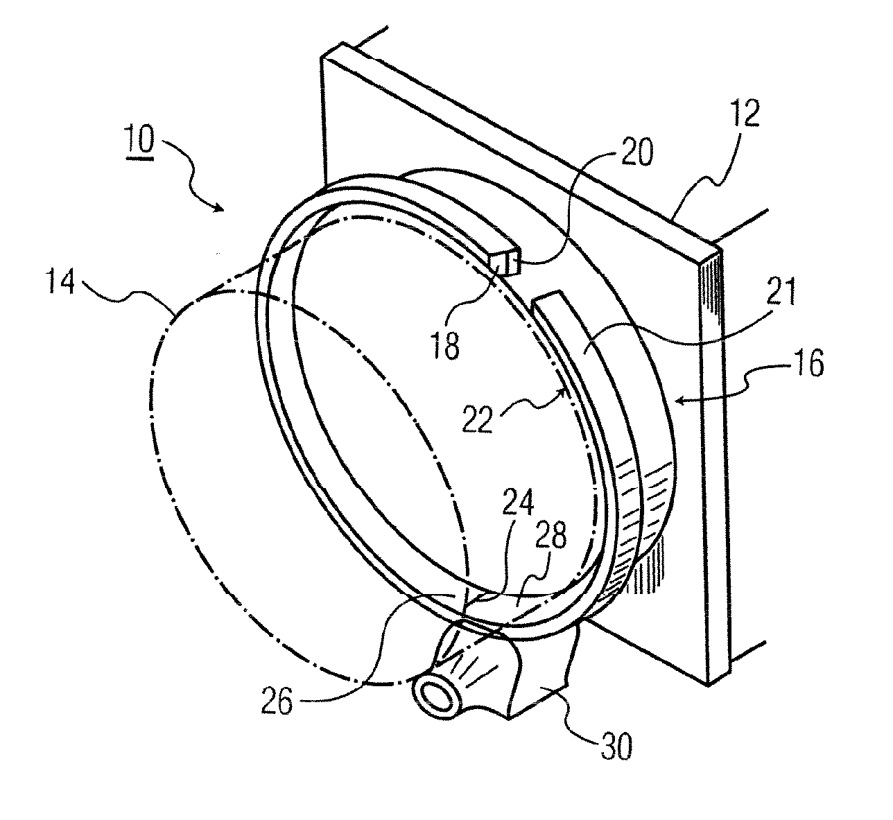
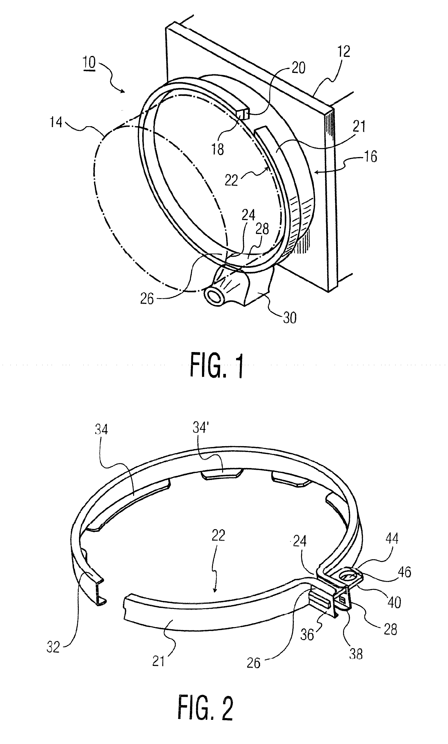
[0045] In FIGS. 1 and 2, meter 10 comprises a base 12 mounted on a support (not shown). A transparent cover 14 is clamped to the base 12 by meter ring clamp assembly 16 in a clamping mode, i.e., locked state, of the assembly. The assembly 16 has locked and unlocked states. The cover 14 has an annular radially outwardly extending flange 18 which abuts an annular radially outwardly extending flange 20 on the base 12. The ring clamp assembly 16 comprises a U-shaped (in portions as described below) generally annular stamped sheet steel ring 22, preferably stainless steel. The ring 22 comprises a base wall 21, an upper radially inwardly directed flange 32 and lower spaced radially inwardly directed flanges 34 and 34′. The base wall 21 and flanges 32, 34, 34′ form an annular channel that receives the cover and base flanges 18, 20 (FIG. 1). The flanges 34, 34′ are of circumferentially different size portions that partially extend about the ring circumference in spaced relationship to each ...


PUM


Abstract

A utility meter clamping ring is locked to the meter by a locking device that locks the free ends of the ring together automatically without the use of a separate plunger device. A latch is spring loaded in the locking device housing in a normally biased lock position. The lock device is secured to one free end of the clamping ring. An apertured blade is attached to the other free end of the clamping ring. The ring is placed about the flanges of the meter cover and base flanges and the blade is then inserted into the locking device housing where its aperture is engaged automatically by the spring loaded latch and locked to the housing upon insertion. A conventional plunger key may optionally be used to unlock the latch and release the blade from the locked position to free the ends for removal of the meter cover via an optional bore in the latch engaged by the key. The latch may be optionally permanently locked to the blade so that either the locking device or the ring has to be destroyed. Weakening grooves are in the ring of the latter embodiment to facilitate breaking the ring open. Embodiments are disclosed for use with F and G type plunger unlock keys and include an anti-tampering sleeve for use in the lock to preclude tampering disengagement of the lock of the type used with an F type key.

Description

[0001] This application claims the benefit of provisional applications Ser. No. 60 / 689,027 filed Jun. 9, 2005; Ser. No. 60 / 725,552 filed Oct. 11, 2005; and Ser. No. 60 / 743,842 filed Mar. 28, 2006, each entitled “Meter Ring Locking Device” and each incorporated by reference herein in its entirety.BACKGROUND OF THE INVENTION [0002] 1. Field of the Invention [0003] This invention relates to meter clamping rings for securing and locking a utility meter cover to its base housing. [0004] 2. Description of the Prior Art [0005] Utility electric meters have transparent covers that are secured to the meter mechanism in a base unit. The covers are typically circular cylindrical transparent glass cup shaped members and have an annular rib at an edge flange. The meter base unit has a circular cylindrical housing with an annular flange that abuts the cover edge flange. A meter ring engages the flanges of the cover and base unit clamping the cover to the base unit housing. [0006] The clamping ring...

Claims


Application Information

Patent Timeline
Patent Type & Authority Applications(United States)
IPC IPC(8): B65D55/14
CPCE05B65/0089Y10T70/5566G01F15/007G01F15/14
Inventor DEBRODY, ROBERT F.DREISBACH, RICHARDPINHO, CARLOS M.
Owner DEBRODY ROBERT F
Why Eureka
Try Eureka