Surface mounted four terminal resistor

Inactive Publication Date: 2007-05-29
VISHAY DALE ELECTRONICS INC
View PDF9 Cites 25 Cited by
  • Summary
  • Abstract
  • Description
  • Claims
  • Application Information

AI Technical Summary

Benefits of technology

[0012]A surface mounted resistor is formed by welding to each side of a resistive strip of Ni—Cr alloy two strips, one narrow and another wide, of a Ni plated high conductivity copper. The thickness and width of the resistive strip are chosen to form a resistance value below but close to the requested target, and therefore to minimize the extent of posterior laser trimming. This composite strip is punched to form individual resistors in a way described in the U.S. Pat. No. 5,604,477, but with an additional slot in the

Problems solved by technology

When applied to ohmic values in the range of a few millohms or less, this construction introduces additional Joule losses due to the resistance between the

Method used


Image

  • Surface mounted four terminal resistor
  • Surface mounted four terminal resistor
  • Surface mounted four terminal resistor

Examples


Embodiment Construction

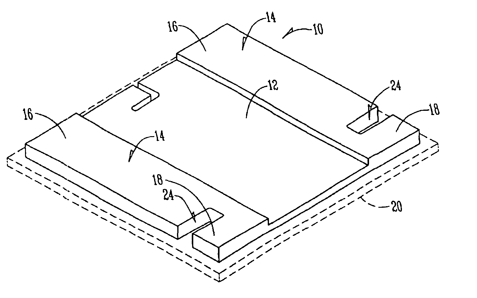
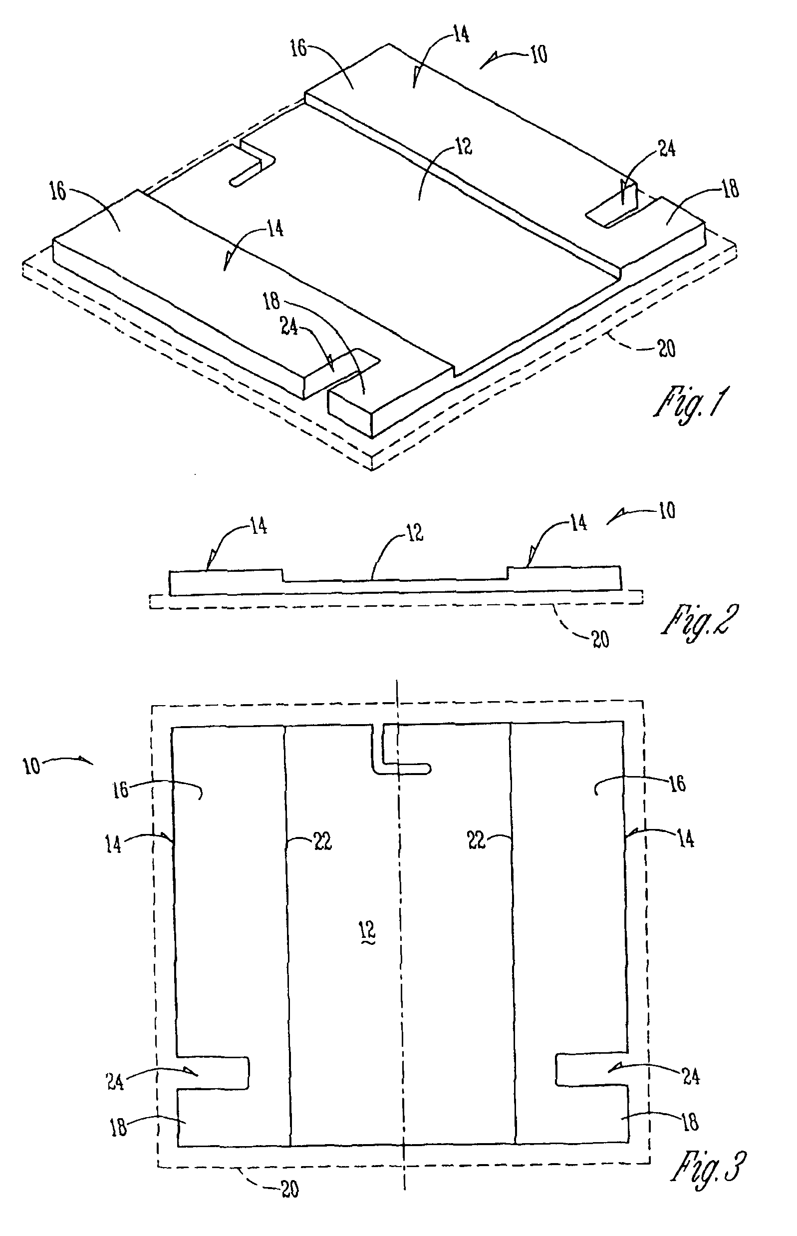
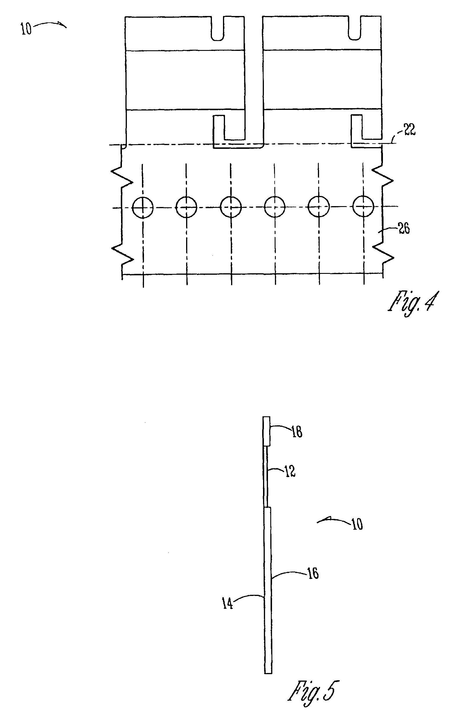
[0020]The numeral 10 designates the resistor of this invention. It includes a resistor plate 12 with a pair of pads 14 secured thereto. Each pad has a current pad portion 16 and a sense pad portion 18. Resistor 10 is adapted for mounting on substrate 20. Specifically, the surface mounted resistor 10 is formed by welding to each side of the resistive strip 12 of Ni—Cr alloy two strips 14, one narrow and another wide, of a Ni plated high conductivity copper. The thickness and width of the resistive strips 12 are chosen to form a resistance value below but close to the requested target, and therefore to minimize the extent of posterior laser trimming. This composite strip is punched on lines 22 (FIG. 4) to form individual resistors 10 in a way described in the U.S. Pat. No. 5,604,477 (incorporated herein by reference), but with an additional slot 24 in the terminations in order to divide them into distinct current and sense pads, the current pad 16 being at least twice as long as the s...


PUM


Abstract

An electrical resistor has a surface mounted four terminal current sensor of a very low resistance value and capable of handling short pulses of high power. It comprises a flat metal late, 1 to 50 mils thick, of an alloy of high electrical resistivity, to which are welded, on two opposite sides, two flat metal plates of very high electrical conductivity which serve as terminations for electrical interconnection. A slot is cut, from the outside edge toward the center, into each of the two termination plates which divides them into a wide pad for connection of current carrying wires and a narrow one for voltage sensing. The depth of the slots is optimized to get the best stability of resistance readings with changing ambient temperature and under influence of the self-heating effect.

Description

[0001]This application is based upon the applicants' provisional application Ser. No. 60 / 074,570 filed Feb. 13, 1998.BACKGROUND OF THE INVENTION[0002]The present invention relates to a surface mounting four terminal current sensing resistor of very low ohmic value and high stability.[0003]Surface mounted current sensing resistors have been available for the electronic market for many years. Their construction comprises a flat plate made of a resistive alloy like the Cu—Mn—Ni alloy onto which are plated lands of high conductivity metal forming the four terminals. The voltage-sensing node is set in the resistive alloy.[0004]When applied to ohmic values in the range of a few millohms or less, this construction introduces additional Joule losses due to the resistance between the point of connection of the current carrying wires and the a / m nodes. This leads to an additional temperature rise and results in drifts of the measurements.[0005]The primary object of this invention is to provid...

Claims


Application Information

Patent Timeline
IPC IPC(8): H01C1/012H01C7/06H01C7/13
CPCH01C7/06H01C7/13
Inventor SZWARC, JOSEPHSMEJKAL, JOEL J.
Owner VISHAY DALE ELECTRONICS INC
Why Eureka
Try Eureka