
Method of forming a perspective rendering from a voxel space

a technology of voxel space and perspective, applied in the field of perspective rendering, can solve problems such as large algorithmic expense, and achieve the effect of approximating divergent perspectives

Inactive Publication Date: 2006-02-14
ALGOTEC SYST
View PDF17 Cites 26 Cited by
  • Summary
  • Abstract
  • Description
  • Claims
  • Application Information

AI Technical Summary

Benefits of technology

[0027]Given the special significance of these front surfaces to the rendering process, an additional layer of processing is introduced. This processing is intended to substantially prevent a situation from occurring wherein two consecutive steps skip over a front surface without detecting it. Continuing in the medical context example, suppose there is a membrane (or thin film of tissue or a bone fragment, etc) in the mucus, that is tangential to the vector. Because the membrane is surrounded by transparent substance, the step size risks “jumping over” the membrane without detecting the existence of the membrane.
[0030]Recalling that the central tradeoff in volume rendering is to provide a feasible method (both visually and algorithmically), the preferred embodiment of the present invention is directed to minimizing the extent to which actual ray-casting is performed. According to a first approximation of this minimizing of ray-casting, a predetermined plurality of rays are cast.
[0050]In step (a), according to the preferred embodiment of the present invention, the spatial resolution of the pixels is higher than that of a cross-section of voxels in the voxel space.
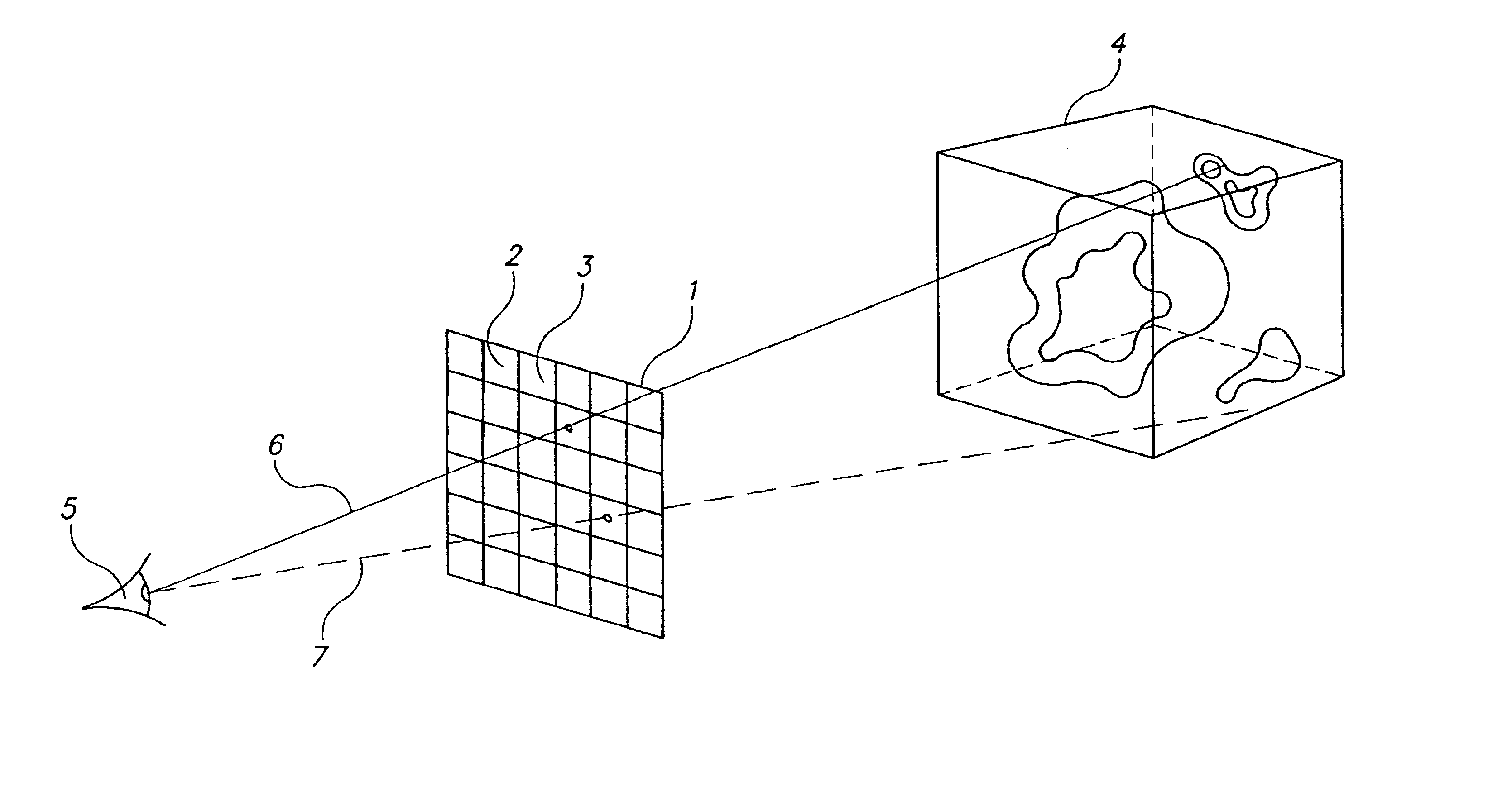
[0051]In step (b), if the vantage-point is far from the virtual window, then the rays cast through the virtual window will effectively be parallel each to another. Alternately, if the vantage-point is close to the virtual window, then the rays cast will effectively be approximating a divergent perspective; as subtended through the angle defined by the virtual window.

Problems solved by technology

Even for intermediate-order interpolations, there is a large algorithmic expense.

Method used


Image

  • Method of forming a perspective rendering from a voxel space
  • Method of forming a perspective rendering from a voxel space
  • Method of forming a perspective rendering from a voxel space

Examples


Embodiment Construction

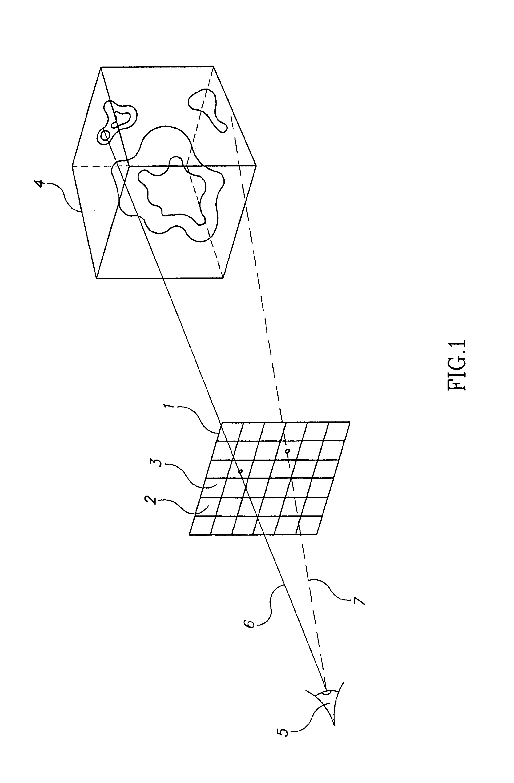
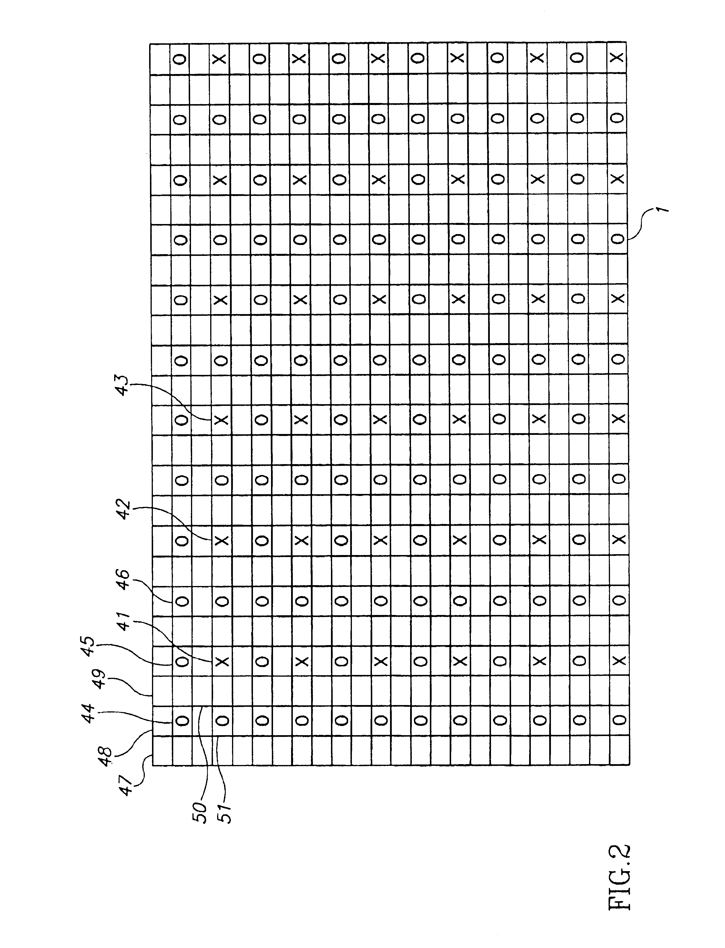
[0075]The present invention relates to a method for forming a high spatial resolution perspective rendering from a low spatial resolution voxel space. (Turning to FIG. 1, which is a schematic diagram of ray-casing geometry. This geometry is a typical geometry that is used in many embodiments of the present invention.) The method includes the four steps of:[0076](a) Initializing a virtual window (1) of predetermined resolution pixels (2) (3), and placing the virtual window in or near the voxel space (4). These pixels are logical storage elements corresponding to coordinates or regions of the virtual window. Normally, there is a simple and direct transformation from the geometry of the pixels of the virtual window to a display device (e.g. CRT, LCD, plotter, etc.).[0077](b) From a predetermined vantage-point (5), sparsely ray-casting a plurality of vectors (6) (7) through the virtual window into the voxel space. (Turning to FIG. 2, which is a schematic mapping of a ray-casting orderin...


PUM


Abstract

A method for forming a high spatial resolution perspective rendering from a low spatial resolution voxel space is disclosed. The method comprises steps of: a) initializing a virtual window of predetermined resolution pixels, and placing the virtual window in or near the voxel space; b) sparsely ray-casting a plurality of vectors from a predetermined vantage-point through the virtual window into the voxel space; and c) calculating a visualization-value at a series of positions along each vector. In a position ordering of steps from the vantage-point to the pixel, an accumulated transparency-value threshold is calculated. Values of proximate voxels are interpolated into an interpolated voxel value for each position. The interpolated voxel values are then transformed into a derived visualization-value and transparency value.

Description

RELATED APPLICATION[0001]This application is a U.S. national filing of PCT Application No. PCT / IL99 / 00639, filed Nov. 26, 1999, the disclosure of which is incorporated herein by reference.FIELD OF INVENTION[0002]This invention relates to a method for forming a perspective rendering from a space of volume elements (voxels). More specifically, this invention relates to a family of algorithmic optimizations, which are useful in the forming of a perspective rendering from a voxel space.BACKGROUND OF THE INVENTION[0003]Many quantitative disciplines collect or generate multidimensional data. These disciplines include medical imaging applications such as CT or MRI; geophysical modeling, meteorological forecasting, scientific simulations, animation models, and the like. This multidimensional data is often stored and manipulated in the form of voxels. Voxels are volume elements in three (or more) dimensions; and are analogous to pixels (two dimensional picture elements).[0004]Professionals o...

Claims


Application Information

Patent Timeline
IPC IPC(8): G06T17/00G06T15/00G06T15/06G06T15/40G06T15/50
CPCG06T15/40G06T15/06
Inventor AKERMAN, SHMUELMILLER, GAD
Owner ALGOTEC SYST
Learn More