Universal mounting technique for video matrix switching with chassis volume reduction

a video matrix and chassis technology, applied in the direction of color television, television system, coupling device connection, etc., can solve the problems of increasing and increasing the size of electronic signal processing circuitry, so as to achieve the effect of reducing the volume of connection apparatus and only increasing the likelihood of spiraling

Inactive Publication Date: 2006-05-04
SENSORMATIC ELECTRONICS CORP
View PDF7 Cites 8 Cited by
  • Summary
  • Abstract
  • Description
  • Claims
  • Application Information

AI Technical Summary

Problems solved by technology

The above-described type of known CCTV system presents great difficulties where the need for repair arises with respect to the electronic signal processing circuit thereof, i.e., the need for correction of a fault occurring therein.
From applicant's perspective, known CCTV connection apparatus, being dictated by the geometry above discussed, does not address the trend toward more and more participating cameras (more and more back plane connectors and xy area) and the ever diminishing size of electronic signal processing circuitry.
Rather, the present undesired volume of connection apparatus (monitoring station real estate being presently excessive) is seen as only likely to further spiral.

Method used


Image

  • Universal mounting technique for video matrix switching with chassis volume reduction
  • Universal mounting technique for video matrix switching with chassis volume reduction
  • Universal mounting technique for video matrix switching with chassis volume reduction

Examples


Embodiment Construction

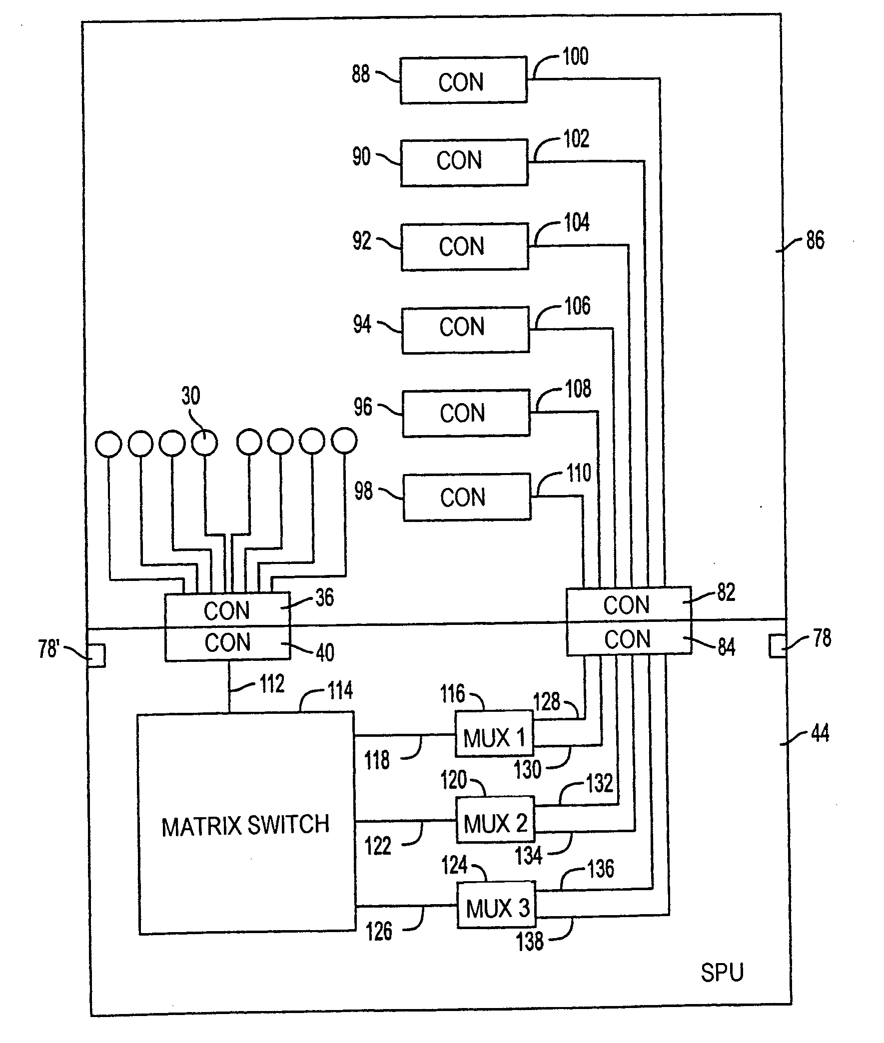
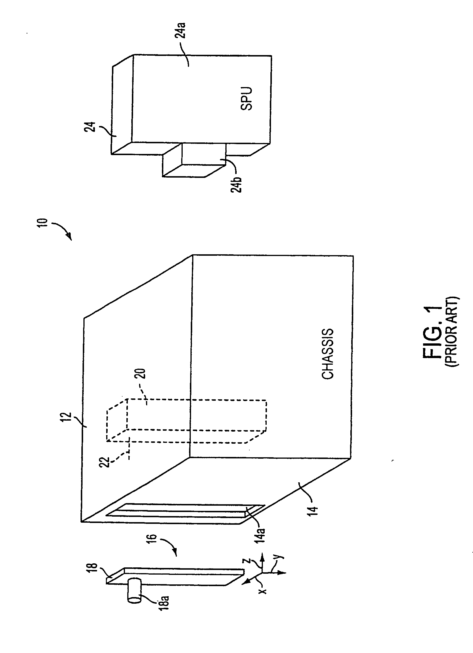
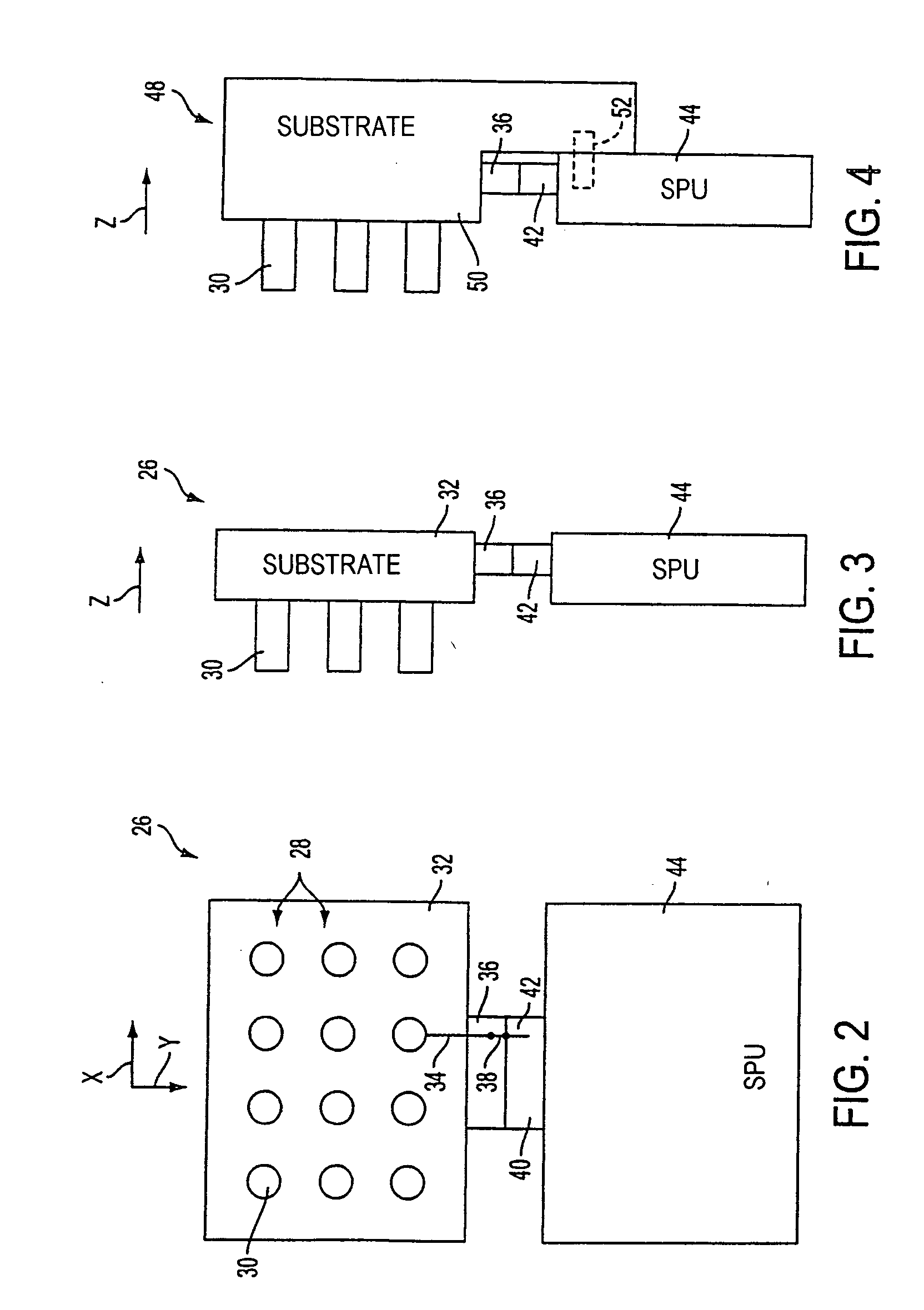
[0045]FIG. 1, an explanatory view generally depicting the above-discussed second known type of CCTV system for article surveillance, shows in exploded fashion video signal connection apparatus 10. Apparatus 10 includes a generally boxed-shaped chassis 12, having back panel 14, which defines a plurality of slots, one being shown at 14a, for the receipt and retention of I / O connection contact units, one being shown at 16, comprising a substrate 18, from which a plurality of video signal connector contacts, i.e., I / O video signal connector contacts, one such contact being shown at 18a, in the form of a BNC male contact connectable with a female contact (not shown) of a video camera (not shown).

[0046] Interiorly of chassis 12 are supported connectors, one being shown at 20, for interconnection with the I / O connection contact units through conductors, conductor 22 being shown for connection of connection contact 18a to connector 20.

[0047] The I / O video signal connector contacts, e.g., ...


PUM


Abstract

A video signal connection apparatus comprises an array of individual video signal connector contacts arranged in a matrix having connector contact rows and connector contact columns, the individual video signal connector contacts extending in a first connection ‘direction, a connector having individual connector contacts corresponding in number to the individual video signal connector contacts of the array, the individual connector contacts extending in a second connection direction, the second connection direction being orthogonal to the first connection direction and conductors interconnecting the individual video signal connector contacts to the individual connector contacts.

Description

CROSS REFERENCE TO RELATED APPLICATIONS [0001] This application is a divisional of U.S. patent application Ser. No. 09 / 614,288, filed Jul. 21, 2000, which is hereby incorporated by reference and is assigned to assignee of the present application.FIELD OF THE INVENTION [0002] This invention relates generally to electrical connection apparatus and pertains more particularly to connection apparatus for use in CCTV (closed circuit television) systems for surveillance applications. BACKGROUND OF THE INVENTION [0003] Known CCTV systems for surveillance applications typically include plural video cameras disposed at locations of interest and a connection apparatus having a so-called “back panel” with input connectors in number corresponding to the plurality of video cameras. Cables extending from the video cameras are terminated with a so-called “BNC” jack connector and the back panel input connectors are BNC socket connectors each receiving one of the cable jack connectors. [0004] In one ...

Claims


Application Information

Patent Timeline
Patent Type & Authority Applications(United States)
IPC IPC(8): H04N7/18H04N5/225H01R31/06H04N5/64
CPCH01R31/06H01R2201/18
Inventor THOMPSON, EDWIN S.CRABLE, WILLIAM A. JR.MULLINS, CHRISTOPHER M.DAVIS, LEROYGELMAN, GREGORYGERMAIN, ROBERT E.HARDING, ALBERTJOHNSON, HAROLD
Owner SENSORMATIC ELECTRONICS CORP
Why Eureka
Try Eureka