Optically enhanced digital imaging system

a digital imaging and optical zoom technology, applied in the field of optical zoom digital imaging systems, can solve the problems of time-consuming adjustments, wear and tear of moving mechanical components in the system, and the inability to adjust the image at the same tim

Inactive Publication Date: 2006-05-04
FORMFACTOR INC
View PDF99 Cites 34 Cited by
  • Summary
  • Abstract
  • Description
  • Claims
  • Application Information

AI Technical Summary

Benefits of technology

[0011] In satisfaction of these needs and others, embodiments of the present invention provide continuous-zoom systems and methods which employ multiple optical pathways and digital zooming techniques. In addition, embodiments of the prov

Problems solved by technology

Due to these abrupt magnification changes, the field of view often crops out interesting objects, requiring time-consuming adjustments to the object's position.
Furthermore, microscopes containing op

Method used


Image

  • Optically enhanced digital imaging system
  • Optically enhanced digital imaging system
  • Optically enhanced digital imaging system

Examples


Embodiment Construction

[0029] The present invention will be more completely understood through the following detailed description, which should be read in conjunction with the attached drawings. In this description, like numbers refer to similar elements within various embodiments of the present invention. Within this detailed description, the claimed invention will be explained with respect to preferred embodiments. However, the skilled artisan will readily appreciate that the methods and systems described herein are merely exemplary and that variations can be made without departing from the spirit and scope of the invention.

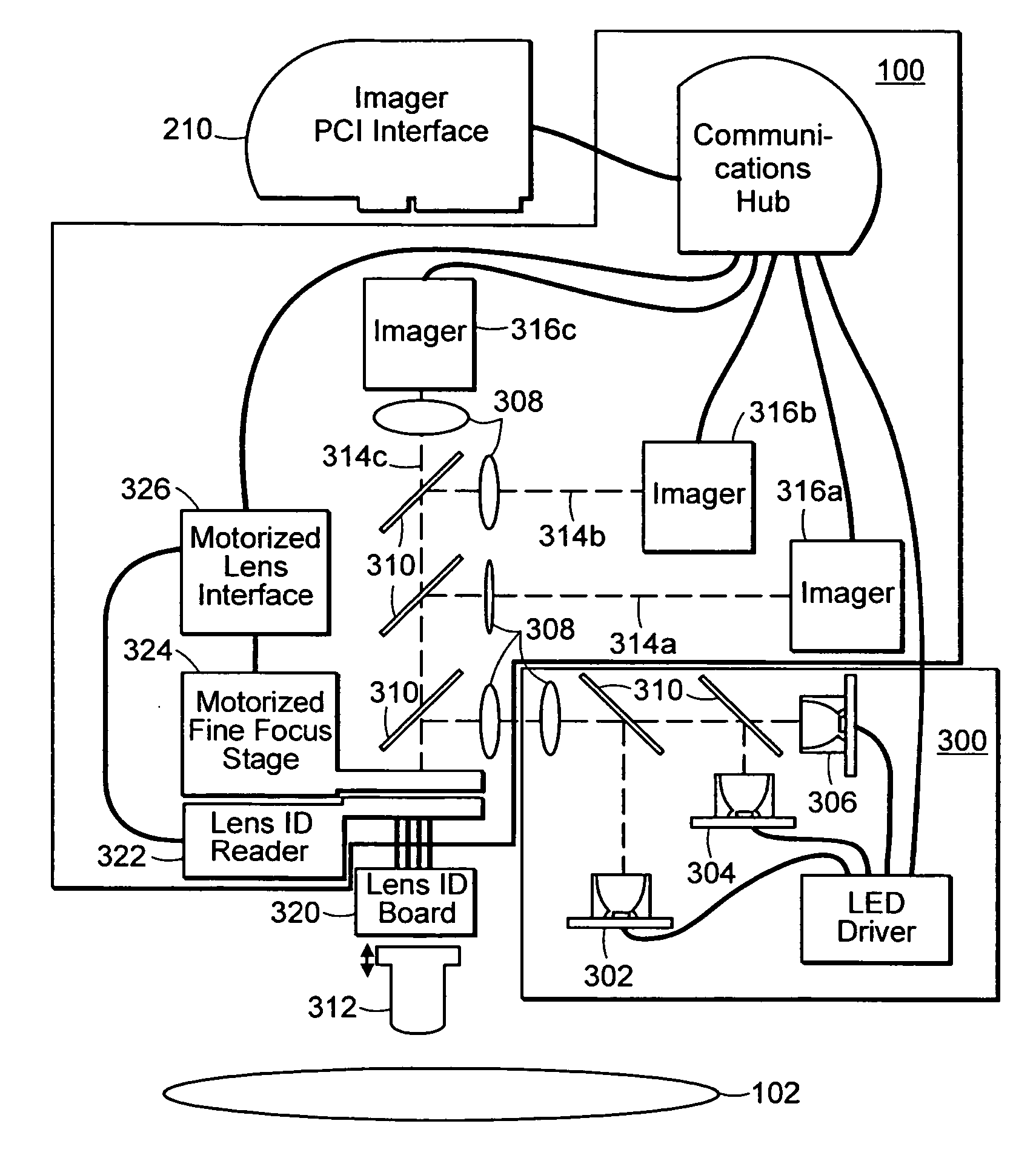
[0030] In general, the present invention comprises a multi-path optical imaging system with continuous digital zoom capability enhancing a plurality of optical magnification levels.

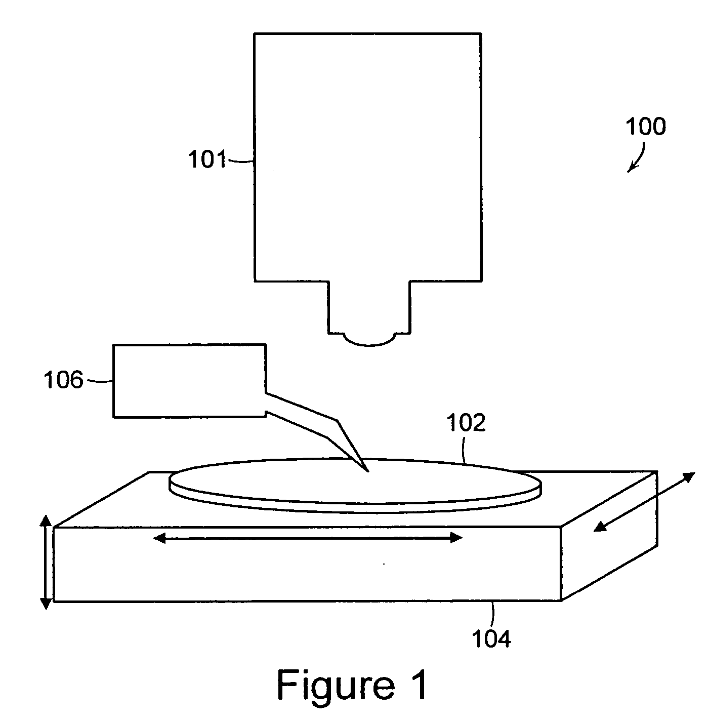
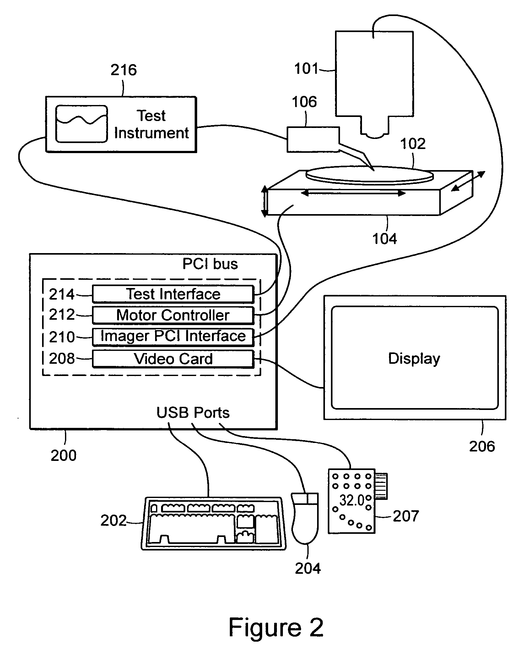
[0031]FIG. 1 is a block diagram illustrating one embodiment of a digital optical probe system 100. The digital optical probe system, 100 includes an imaging system 101, a movable stage 104, a target spec...


PUM


Abstract

Improved methods and systems for imaging are provided. Specifically, systems and methods for extending the range of a digital zoom are provided in which an imaging system provides continuous magnification over a plurality of interleaved optical pathways and digital zooming imagers. Systems and methods of centering an image as the field of view changes, and for masking out undesirable obstacles from a magnified image are also provided.

Description

CROSS-REFERENCE TO RELATED APPLICATION [0001] This application claims the benefit of U.S. Provisional Patent Application No. 60 / 624,326 filed Nov. 2, 2004 the entire disclosure of which is incorporated herein by reference.FIELD OF THE INVENTION [0002] The present invention relates to optically enhanced digital imaging systems, and specifically to improved systems and methods for multi-path optical magnification of a digitally zoomable image. BACKGROUND OF THE INVENTION [0003] Many scientific and engineering applications require individuals to be able to see and manipulate items which are not visible with the naked eye. Semiconductor manufacturers, for example, must be able to examine and probe micro and nano-scale circuits fabricated on various substrates. Similarly, biological researchers must be able to see and manipulate cells, proteins, micro-organisms and other microscopic elements within their laboratories. Microscopic and metrologic applications are as prevalent and diverse a...

Claims


Application Information

Patent Timeline
IPC IPC(8): G02B21/00
CPCG02B21/025G02B21/18G02B21/365G06T3/4069H04N1/393H04N5/23296H04N23/69
Inventor ABNET, CHARLES CAMERONFELDKHUN, DANIEL LEIBOVICHMERMELSTEIN, MICHAEL STEPHEN
Owner FORMFACTOR INC
Why Eureka
Try Eureka