Corner connection block for assembly container

a technology for connecting blocks and assembly containers, applied in the direction of connecting rods, girders, dismountable cabinets, etc., can solve the problem of inability to reuse, and achieve the effect of fast and firm connection of frames

Inactive Publication Date: 2006-05-11
GREEN HOPE CORP
View PDF12 Cites 4 Cited by
  • Summary
  • Abstract
  • Description
  • Claims
  • Application Information

AI Technical Summary

Benefits of technology

[0006] The present invention is mainly applied to a corner connection block for connecting frames at each corner of an assembly container, such as an assembly cabinet, an assembly drawer, or an assembly box, etc, with two frames formed at each corner and a hole formed on each end of a frame, to be inserted by rods formed beneath a base of the corner connection block, wherein the base is with a fixed thickness and each rod formed paralleling to the other, thereby enabling a fast and firm connection of frames for a layer of the assembly container.

Problems solved by technology

Besides being complicated in screwing and assembling process, the screwing to assemble method may cause holes thereof damaged or enlarged excessively to the extent that a re-use is impossible.

Method used


Image

  • Corner connection block for assembly container
  • Corner connection block for assembly container
  • Corner connection block for assembly container

Examples


Embodiment Construction

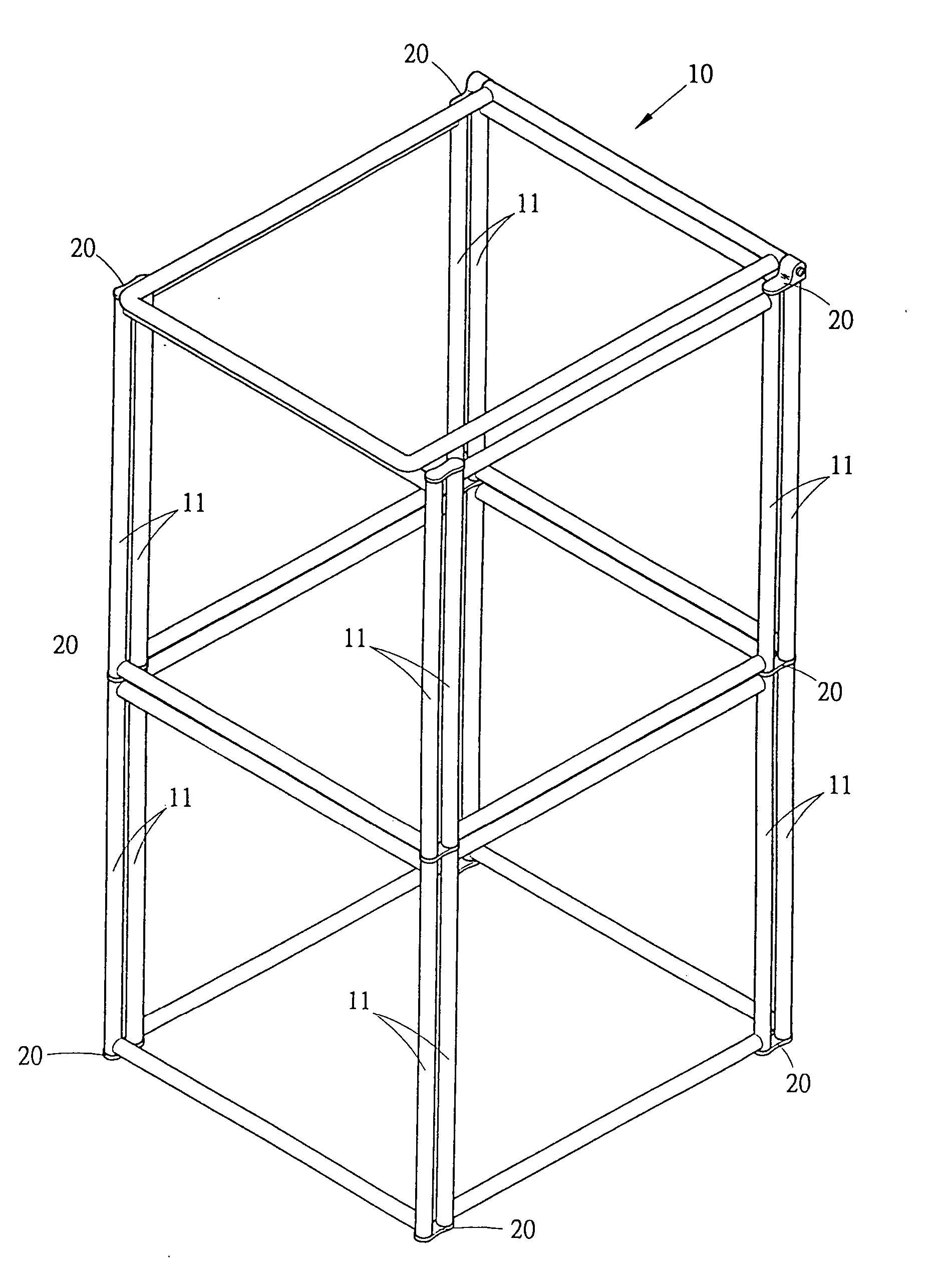
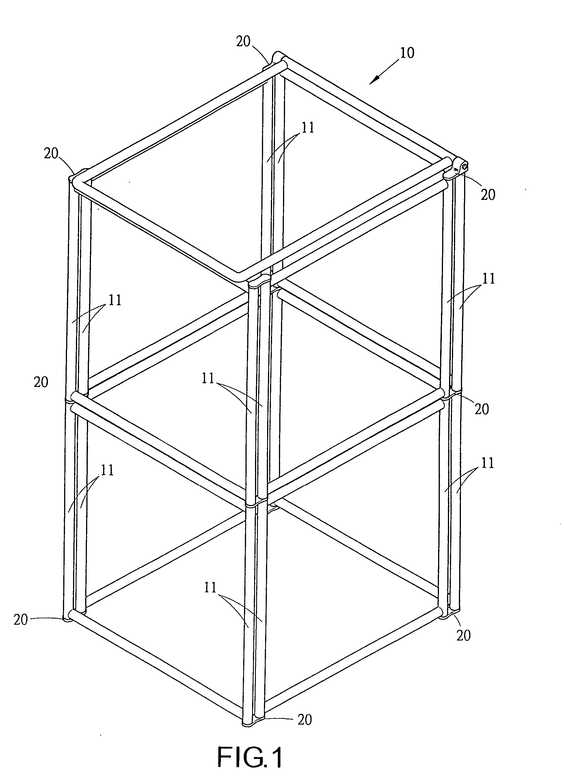
[0015] Referring to FIGS. 1 and 2. An application, an assembly cabinet 10 (or an assembly drawer, or assembly box, or an assembly frame, etc), to be surrounded by weaving material of cloth or rattan, is formed by circular tube frames 11 on each corner, wherein a hole 12 formed on each end of a frame, to be inserted by a corner connection block 20 to form a connection with other frames.

[0016] Referring to FIGS. 2 and 3. The corner connection block 20 is formed by a base 21 having a fixed thickness, wherein two cylinder rods 22, paralleling to each other, formed beneath the base 21, to be inserted into holes 12 thereof to connect frames, thereby forming a layer of an assembly container. The corner connection block 20 can be formed with a flat surface to enhance appearance. Additionally, rods 22 thereof can also be formed on the base 21, each in align with rods formed beneath the base 21, thereby forming an upper and a lower layer of an assembly container.

[0017] Referring to FIG. 4. ...


PUM


Abstract

The present invention is chiefly applied to a corner connection block for connecting frames at each corner of an assembly container, such as an assembly cabinet, an assembly drawer, or an assembly box, etc with a fixed thickness base, wherein two rods, paralleling to each other, formed beneath, to be inserted in holes formed on each end of a frame, thereby firmly connecting two adjacent frames.

Description

BACKGROUND OF THE INVENTION [0001] (a) Field of the Invention [0002] The present invention relates to a corner connection block, in a form of an unity, for connecting frames of an assembly container, such as an assembly cabinet, an assembly drawer, an assembly box, or an assembly frame, etc and more particularly to utilize corner connection blocks to make fast and firmly connection of frames at each corner of assembly containers thereof. [0003] (b) Description of the Prior Art [0004] Before shipping, to save packaging space, an assembly container, such as an assembly cabinet, an assembly drawer, an assembly box, or an assembly frame, etc is usually in a disassembled form of frames and plates to facilitate packing into a (carton) box. By assembling frames and plates thereof according to drawings provided, the assembly container thereby formed. [0005] A conventional assembly container is usually formed with holes on each frame or plate, to be connected by screws to fasten each corresp...

Claims


Application Information

Patent Timeline
Patent Type & Authority Applications(United States)
IPC IPC(8): E04C3/02
CPCA47B47/005E04B1/585F16B7/04F16B12/40
Inventor CHEN, CHI-CHUAN
Owner GREEN HOPE CORP
Why Eureka
Try Eureka