
Power tool having lubricant leakage preventing structure

Active Publication Date: 2006-05-11
HITACHI KOKI CO LTD
View PDF11 Cites 20 Cited by
  • Summary
  • Abstract
  • Description
  • Claims
  • Application Information

AI Technical Summary

Benefits of technology

[0007] It is therefore, an object of the present invention to provide a power tool that suppresses expansion of the air in the mechanism chamber and prevents the lubricant encapsulated in the mechanism chamber from being leaked outside of the mechanism chamber to thereby increase quality and durability of the tool.
[0008] This and other objects of the invention will be attained by a power tool including a housing, an electric motor, a speed change mechanism, a communication forming portion, and a communication passage forming member. The housing defines therein a mechanism chamber, and a lubricant is inserted in an interior of the mechanical chamber. The electric motor is accommodated in the housing. The speed change mechanism is disposed in the mechanism chamber and is connected to the motor for shift-transmitting rotation of the motor. The communication forming portion is provided in the housing. The communication passage forming member is fitted in the communication forming portion for providing a communication passage communicating an interior of the mechanism chamber with an exterior of the mechanism chamber. The communication passage forming member provides at least one impediment portion that restrains leakage of the lubricant to the exterior of the mechanism chamber.

Problems solved by technology

Therefore, a high temperature increases fluidity, with the result that the soap base and oil component tend to be separated from each other.
The leakage of the grease may not only degrade quality and durability of the product, but also smear a working area.
Therefore, relatively a large amount of grease having high fluidity needs to be put in the mechanism chamber.
Further, a heat generated by the high speed reciprocation motion significantly increases pressure in the mechanism chamber.

Method used


Image

  • Power tool having lubricant leakage preventing structure
  • Power tool having lubricant leakage preventing structure
  • Power tool having lubricant leakage preventing structure

Examples


first embodiment

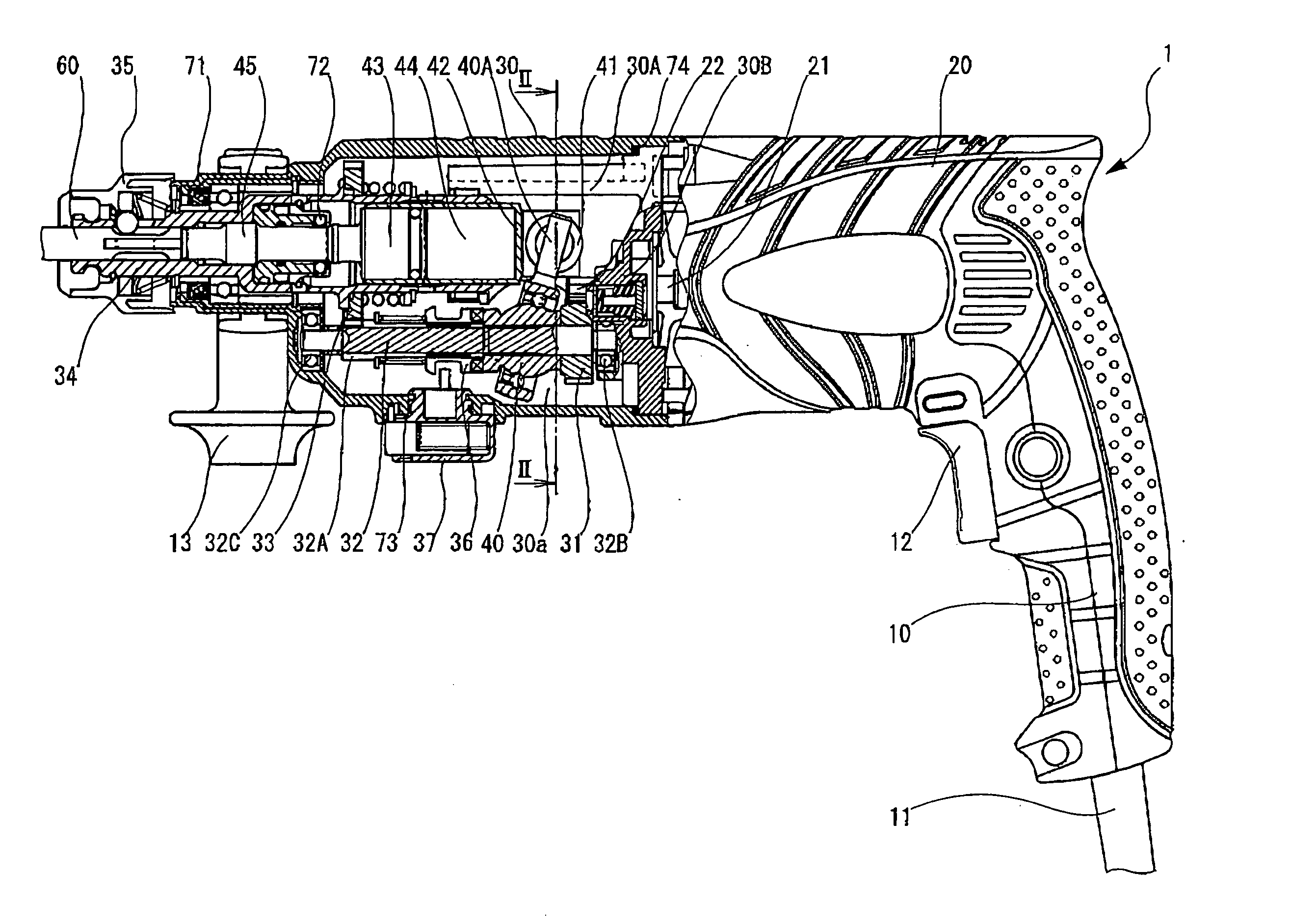
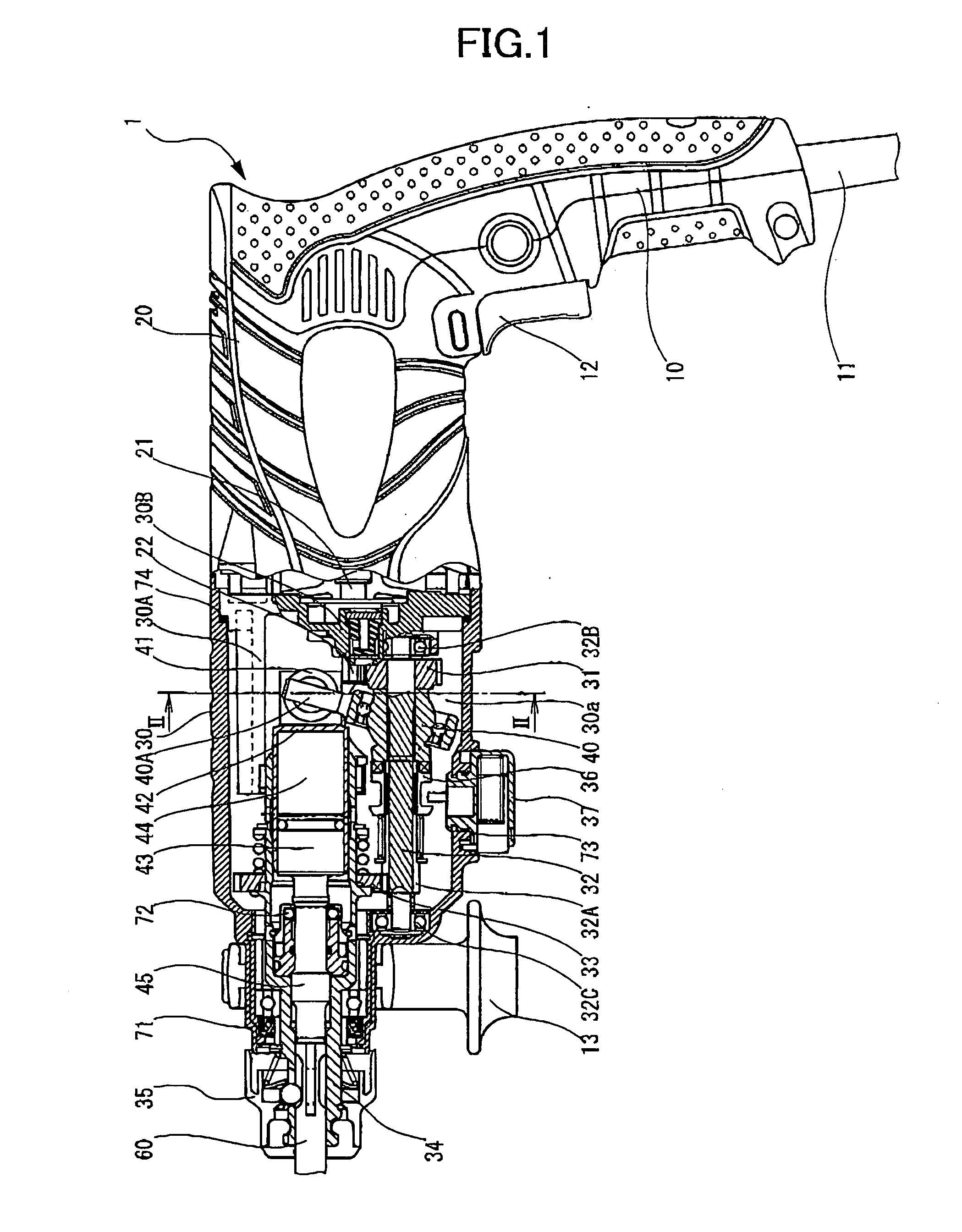
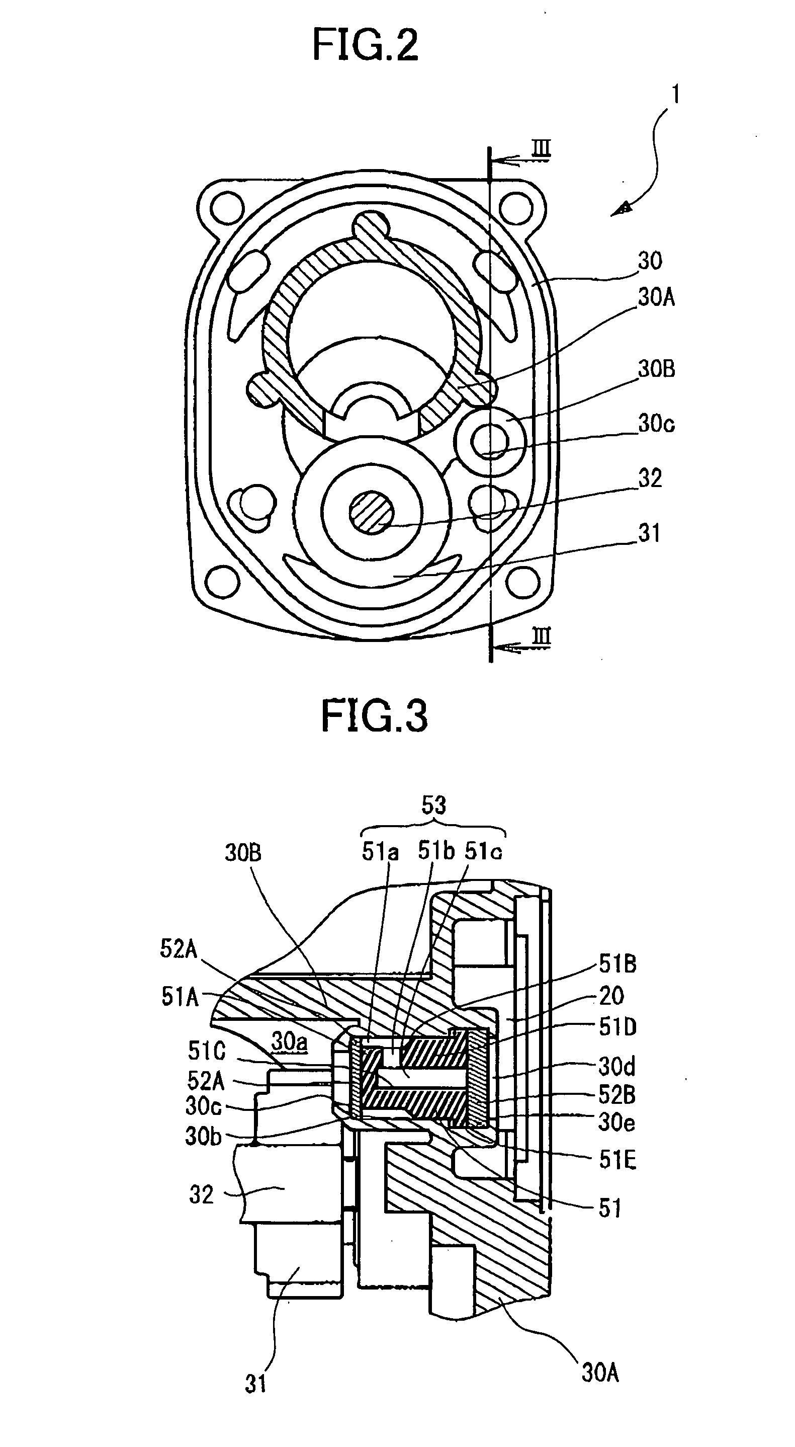
[0019] A power tool according to the present invention will be described below with reference to FIGS. 1 to 3. The power tool is, as shown in FIG. 1, a hammer drill 1 including a handle portion 10, a motor housing 20, and a gear housing 30 those constituting a casing.

[0020] An electric cable 11 is attached to, and a switch mechanism (not shown) is incorporated in the handle portion 10. To the switch mechanism, a user-operable trigger 12 is mechanically connected. The electric cable 11 connects the switch mechanism to an external power supply (not shown). A user operates the trigger 12 to thereby switch connection and disconnection between the switch mechanism and power supply.

[0021] The motor housing 20 is provided above the handle portion 10. The handle portion 10 and motor housing 20 are integrally formed from plastic material. An electric motor (not shown) is housed in the motor housing 20. The motor housing 20 has an output shaft 21 for outputting a driving force.

[0022] The gea...

sixth embodiment

[0095] In the sixth embodiment, another filter made from a material coarser than that of the filter 652B can be disposed in the communication portion 630b at the portion near the inlet 630c to trap the soap base in the grease component. This further prevents the grease component from being discharged to the atmosphere.

[0096] While the invention has been described in detail and with reference to specific embodiments thereof, it would be apparent to those skilled in the art that various changes and modifications may be made therein without departing from the spirit and scope of the invention. For example, although the communication passage forming component is made from the rubber material, oil resistant resin is also available. Alternatively, the communication passage forming component may be made from a metal. In the latter case, when the communication passage forming component is fixed to the communication portion, it is only necessary to force-fit the communication passage forming...


PUM

PropertyMeasurementUnit
Diameteraaaaaaaaaa
Elasticityaaaaaaaaaa
Expansion enthalpyaaaaaaaaaa

Abstract

A power tool suppressing expansion of the air in a chamber and preventing lubricant encapsulated in the chamber from being leaked outside of the chamber. A communication portion communicates a speed reduction chamber with a motor housing communicating with an atmosphere. A communication passage forming component made from an elastic material is fittingly inserted into the communication portion which forms a communication passage including a plurality of impediment portions. When the air containing lubrication component is passed through the communication passage, the air collides against the impediment portions, allowing grease component to be adhered to the impediment portions.

Description

BACKGROUND OF THE INVENTION [0001] The present invention relates to a power tool having a mechanism for transmitting a rotation of an electric motor, and more particularly, to such power tool having a structure for preventing leakage of lubricant. [0002] An electronic motor is mounted in the housing of a power tool such as a hammer drill. A cylinder driven by the electric motor is rotatably supported at the leading end of the housing, and an end tool is attached to the leading end of the cylinder. Further, a speed reduction mechanism is provided in the housing. Through the speed reduction mechanism, a rotation of the electric motor is transmitted to the end tool. [0003] The speed reduction mechanism is housed in a mechanism chamber defined by the housing and has a rotation transmission mechanism including a gear and an intermediate shaft. A rotation of the electric motor is transmitted to the intermediate shaft by the gear and then transmitted to the end tool. A bearing is provided ...

Claims


Application Information

Patent Timeline
IPC IPC(8): B25D11/00
CPCB25D2250/185B25D2250/191B25F5/001
Inventor OOKUBO, TAKAHIRO
Owner HITACHI KOKI CO LTD
Learn More