
System and method for controlling the speed of a tape drive

Inactive Publication Date: 2006-05-11
CERTANCE
View PDF21 Cites 2 Cited by
  • Summary
  • Abstract
  • Description
  • Claims
  • Application Information

AI Technical Summary

Problems solved by technology

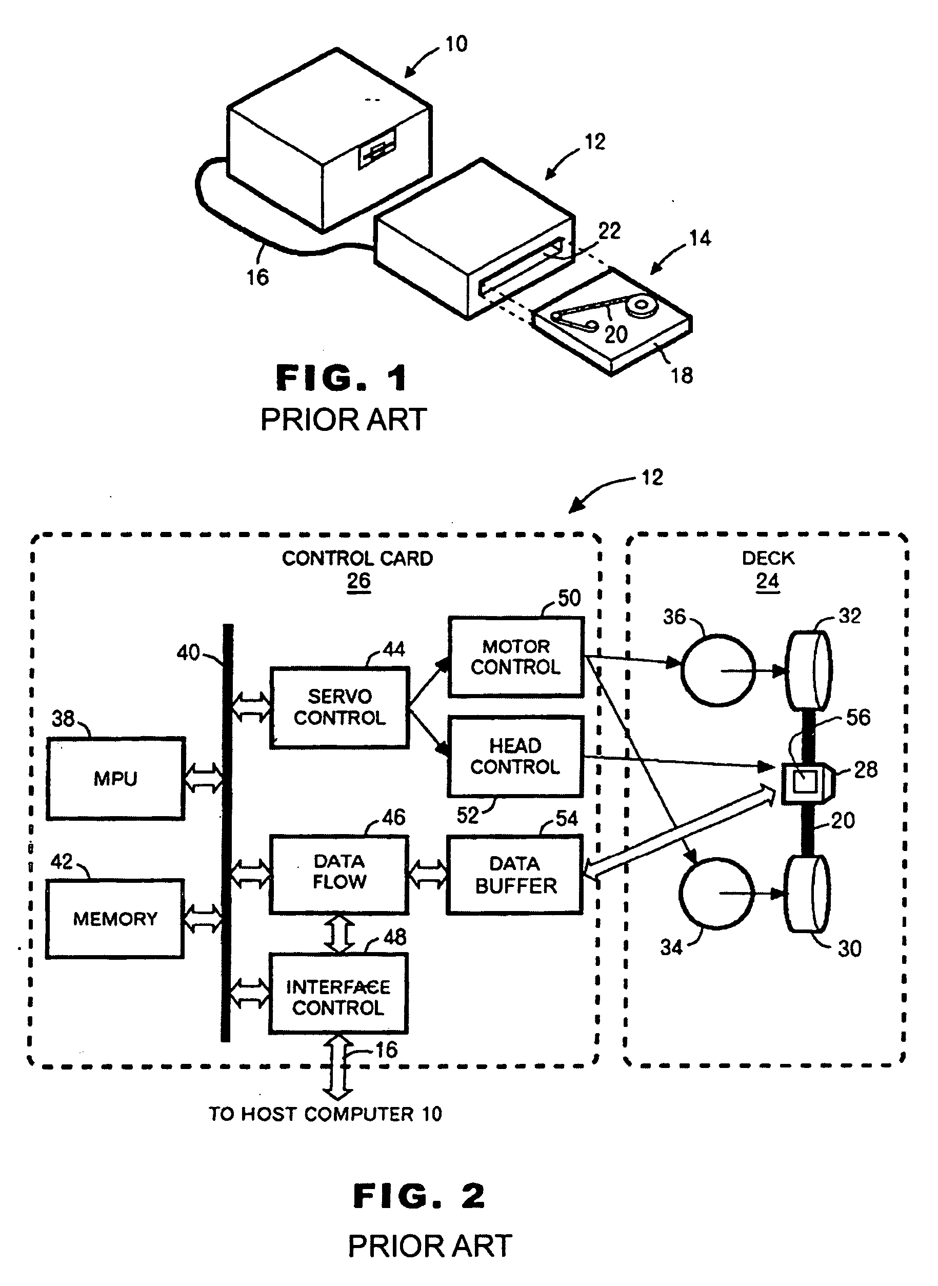
In actual applications this is generally not the case and the tape drive can be used with a variety of computers having different transfer rates, which therefore affects the overall system transfer rate.
For instance, a fast, state of the art tape drive when used with a slow host can actually result in very slow overall system performance due to the fact that the drive must frequently do repositioning in order to wait for the slow host.
However, the current systems to control the speed of the drives suffer from certain shortcomings.

Method used


Image

  • System and method for controlling the speed of a tape drive
  • System and method for controlling the speed of a tape drive
  • System and method for controlling the speed of a tape drive

Examples


Embodiment Construction

[0025] Embodiments of the present invention are described herein in the context of a system and method for tape drive control. Those of ordinary skill in the art will realize that the following detailed description of the present invention is illustrative only and is not intended to be in any way limiting. Other embodiments of the present invention will readily suggest themselves to such skilled persons having the benefit of this disclosure. Reference will now be made in detail to implementations of the present invention as illustrated in the accompanying drawings. The same reference indicators will be used throughout the drawings and the following detailed description to refer to the same or like parts.

[0026] In the interest of clarity, not all of the routine features of the implementations described herein are shown and described. It will, of course, be appreciated that in the development of any such actual implementation, numerous implementation-specific decisions must be made i...


PUM


Abstract

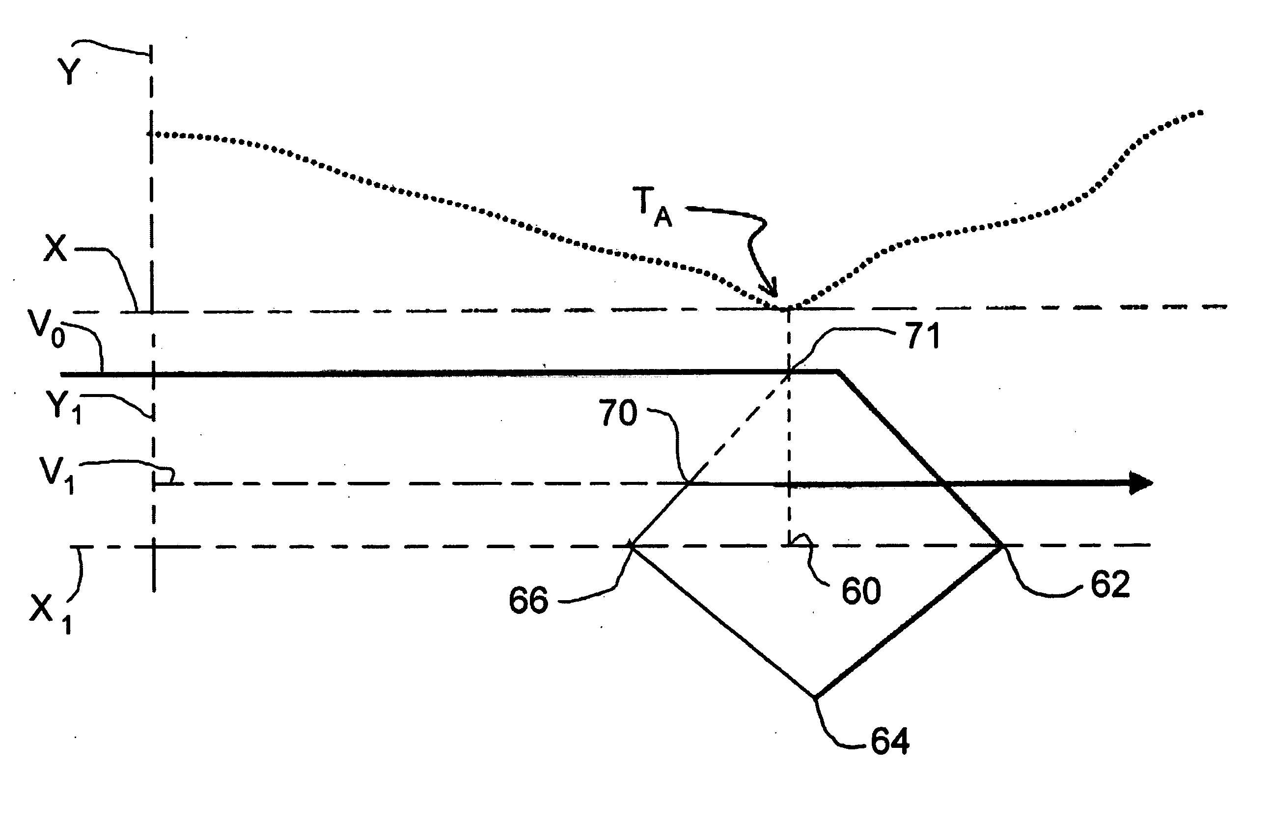
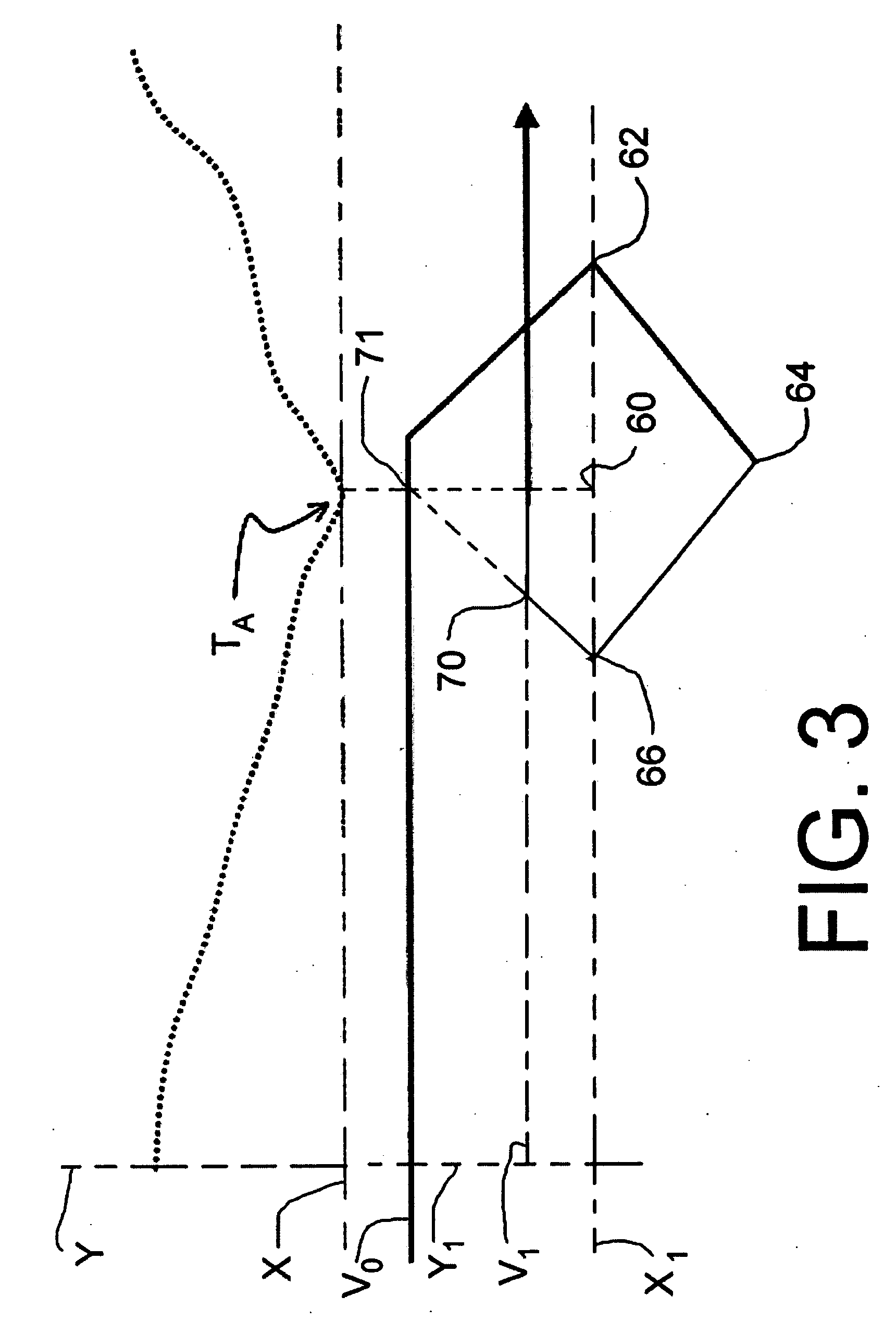
A control system and method for operating a system comprising a host computer, a buffer, a tape drive and a tape is provided. The method includes writing data to the tape while the tape is traveling at a first speed; stopping the tape; determining an optimum second speed to drive the tape to travel; and, thereafter driving the tape to travel at the second speed while writing data to the tape.

Description

FIELD OF THE INVENTION [0001] The present invention relates to tape drives. More particularly, the present invention relates to control of the speed of a tape drive. BACKGROUND OF THE INVENTION [0002] High-density recording on multiple tracks of a magnetic tape is known. In certain arrangements, parallel tracks extend along a longitudinal direction of the magnetic tape. The magnetic tape is moved transversely across a read / write head and data is recorded or read. [0003] Many conventional tape drives are used to back up data stored on the hard disc drive of a computer system. Generally the speed at which the hard disc system can deliver data differs from the speed at which the tape drive can record data and in such cases a data buffer is used. The data is read from the hard disc drive or “host” computer and stored on the data buffer and then the data is transmitted from the data buffer to be recorded on the tape drive. [0004] When a data buffer is used, repositions and under runs of ...

Claims


Application Information

Patent Timeline
IPC IPC(8): G11B15/46
CPCG11B15/20
Inventor GOKER, TURGUYLE, HOA Q.COOPER, STEPHEN C.
Owner CERTANCE
Learn More