Servo control in tape drives

a technology of servo control and tape drive, which is applied in the direction of mechanical tension control of carriers, instruments, recording signal processing, etc., can solve the problems of loss of signal-to-noise ratio, intertrack interference becomes critical, and character interference increases

Inactive Publication Date: 2009-12-24
IBM CORP
View PDF12 Cites 52 Cited by
  • Summary
  • Abstract
  • Description
  • Claims
  • Application Information

AI Technical Summary

Benefits of technology

[0019]A third embodiment of the present invention provides a servo control method for a tape drive having a read / write head for reading and writing data on magnetic tape with at least one servo track for providing transverse position information. The method includes the steps of: reading at least one servo track during read / write operations concurrently with at least two servo readers associated with the read / write head to generate respective servo read signals; processing each servo read signal to generate a series of position values, corresponding to respective time instants, indicative of transverse position of the associated servo reader; and calculating from the position values and time instants (i) a skew value, indicative of tape skew relative to the read / write head, and (ii) a tension variation value indicative of variation of tape tension from a reference value. The calculation accounts for cross-coupling between tape skew and tension variation.

Problems solved by technology

In the former case, the distance between adjacent bit cells decreases, leading to an increase in interference between characters.
Higher track density implies narrower track width, narrower read / write heads and closer head spacing, leading to losses in signal-to-noise ratio.
Also, issues of intertrack-interference become critical.
Among the main problems adversely affecting the performance of track following and reel-to-reel servomechanisms, as well as the quality of readback signals in data channels, are the dynamic skew and the variation of tape tension.
Dynamic skew arises when the head does not remain perfectly perpendicular relative to the direction in which the tape moves.
Tape skewing with respect to the head during tape motion tends to produce increasing loss of signal as frequency rises as well as readback-signal frequency fluctuations.
These cannot easily be tracked by the phase-lock loops that are usually implemented in detection systems.
Moreover, tape skewing introduces delays in the data channels that have to be estimated and compensated for.
In tape transport, this problem is particularly serious when the reel rotation frequencies are near the resonance frequency determined by the tape path.
Tape tension errors affect the position error signal and hence the performance of track following servo.

Method used


Image

  • Servo control in tape drives
  • Servo control in tape drives
  • Servo control in tape drives

Examples


Embodiment Construction

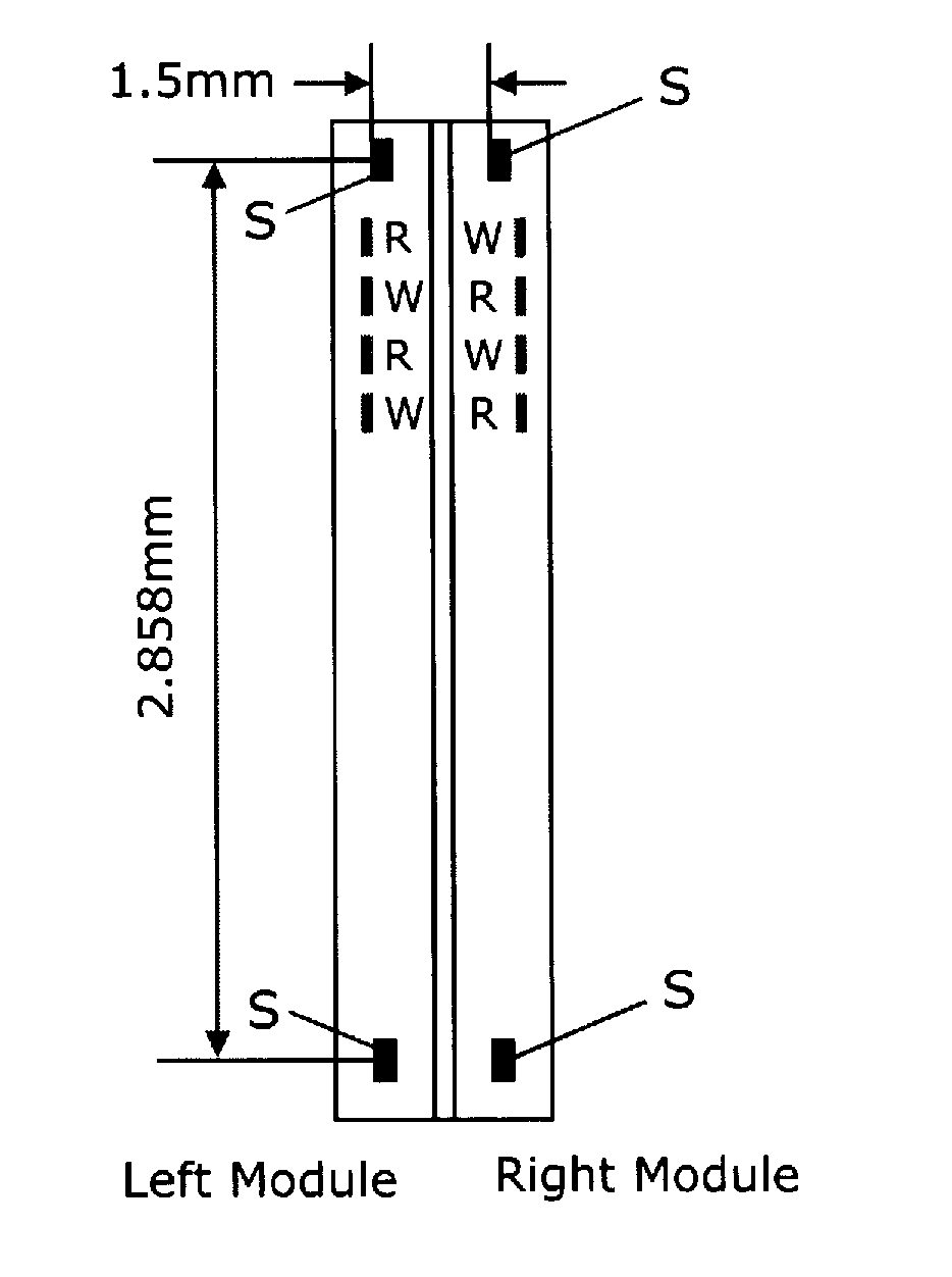
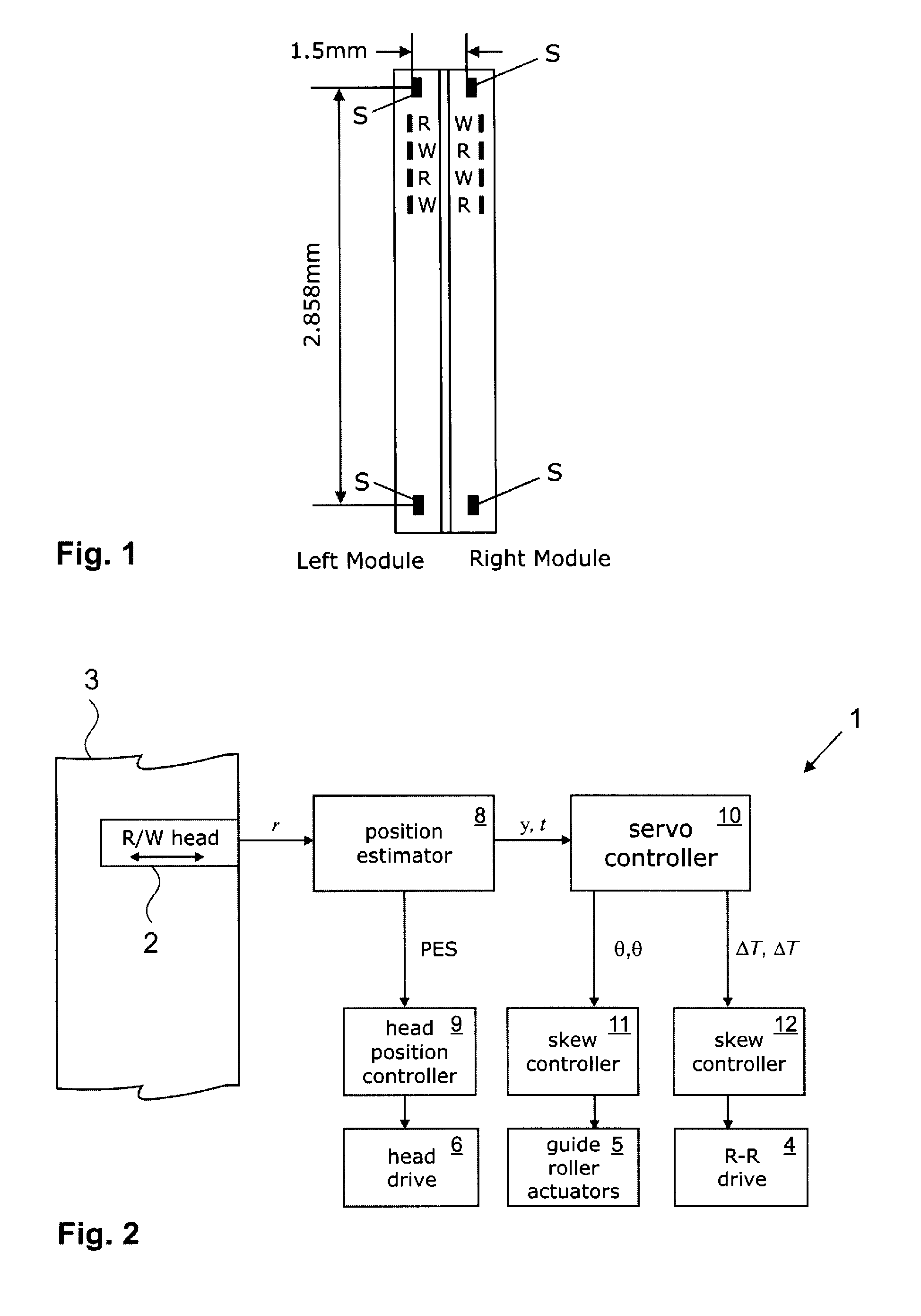
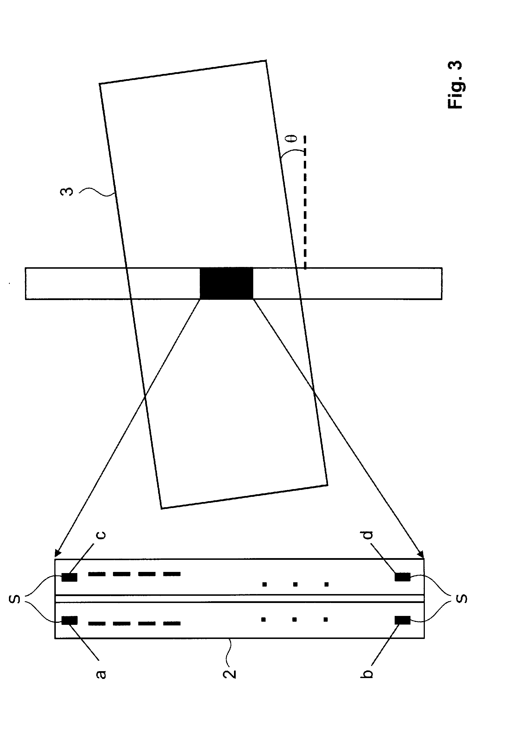
[0027]Servo control apparatus embodying the present invention uses values indicative of transverse position of each of two or more servo readers, and timings associated with these position values, to estimate both tape skew and tension variation jointly during read / write operations. In the preferred embodiments, not only are values for both quantities calculated in operation, the calculation also takes account of cross-coupling between tape skew and tension variation, i.e. the effect of one quantity on the other. This offers exceptional efficiency in servo control functions, allowing corrections for both tape skew and tension variations to be made at the same time, and to a high degree of accuracy, during normal read / write operations. By using the transverse position values and associated timings, this joint estimation of skew and tension variation can be performed based on read signals from any two servo readers operating concurrently, whether reading the same or different servo tr...


PUM


Abstract

Servo control methods and apparatus for a tape drive. A read/write head reads and writes data on magnetic tape with at least one servo track providing transverse position information. At least two servo readers arranged for reading a servo track associated with the read/write head operate concurrently to generate servo read signals. A position estimator processes each servo read signal to generate a series of position values corresponding to respective time instants indicative of their transverse positions. A servo controller calculates a skew value indicative of tape skew relative to the read/write head and a tension variation value indicative of variation of tape tension. The servo controller is adapted to account for cross-coupling between tape skew and tension variation.

Description

CROSS REFERENCE TO RELATED APPLICATION[0001]This application claims priority under 35 U.S.C. 119 from European Patent Application Number 08104461.2, filed Jun. 18, 2008, the entire contents of which are incorporated herein by reference.BACKGROUND OF THE INVENTION[0002]1. Field of the Invention[0003]The present invention relates generally to servo control in tape drives. In particular, the present invention provides control methods and apparatus for use with magnetic tape having one or more servo tracks providing transverse position information during read / write operations.[0004]2. Description of Related Art[0005]In recent years, the capacity and performance of tape storage systems has increased considerably, and the potential for further growth appears to be substantial. In order to achieve higher cartridge capacities and improved performance, advances in several technical areas are necessary. Areal density increase, i.e. increase in linear and / or track density, is key to achieving ...

Claims


Application Information

Patent Timeline
Patent Type & Authority Applications(United States)
IPC IPC(8): G11B5/584G11B20/20
CPCG11B5/58G11B5/596G11B15/43G11B15/093
Inventor CHERUBINI, GIOVANNIJELITO, JENSLANTZ, MARK ALFRED
Owner IBM CORP
Why Eureka
Try Eureka