Reel lock and coupling engagement mechanisms for a cartridge

Inactive Publication Date: 2001-11-20
QUANTUM CORP
View PDF4 Cites 45 Cited by
  • Summary
  • Abstract
  • Description
  • Claims
  • Application Information

AI Technical Summary

Benefits of technology

These and other needs are met by certain embodiments of the present invention which provide a tape cartridge that overcomes the disadvantages of external reel locks and magnetic couplings by employing internal reel lockin

Problems solved by technology

These conventional external reel locks are disadvantageous because they are complex and require a large number of parts, which makes them unreliable and costly.
Furthermore, because they have a number of separate mechanisms which must operate separately when the cartridge is loaded into the tape drive, they slow down the operation of the tape drive.
Disadvantageously, the condition of zero force between the steel plate and the magnet may not be attainable in the short distance desired for coupling engagement/disengagement travel; that is, if there is limited space available between the steel plate and the magnet.
Thus, in applications in which compactness is at a premium, complete disengagement (zero force) may not be achievable with magnetic coupling.
Another disadvantage to the magnetic coupling sche

Method used


Image

  • Reel lock and coupling engagement mechanisms for a cartridge
  • Reel lock and coupling engagement mechanisms for a cartridge
  • Reel lock and coupling engagement mechanisms for a cartridge

Examples


Embodiment Construction

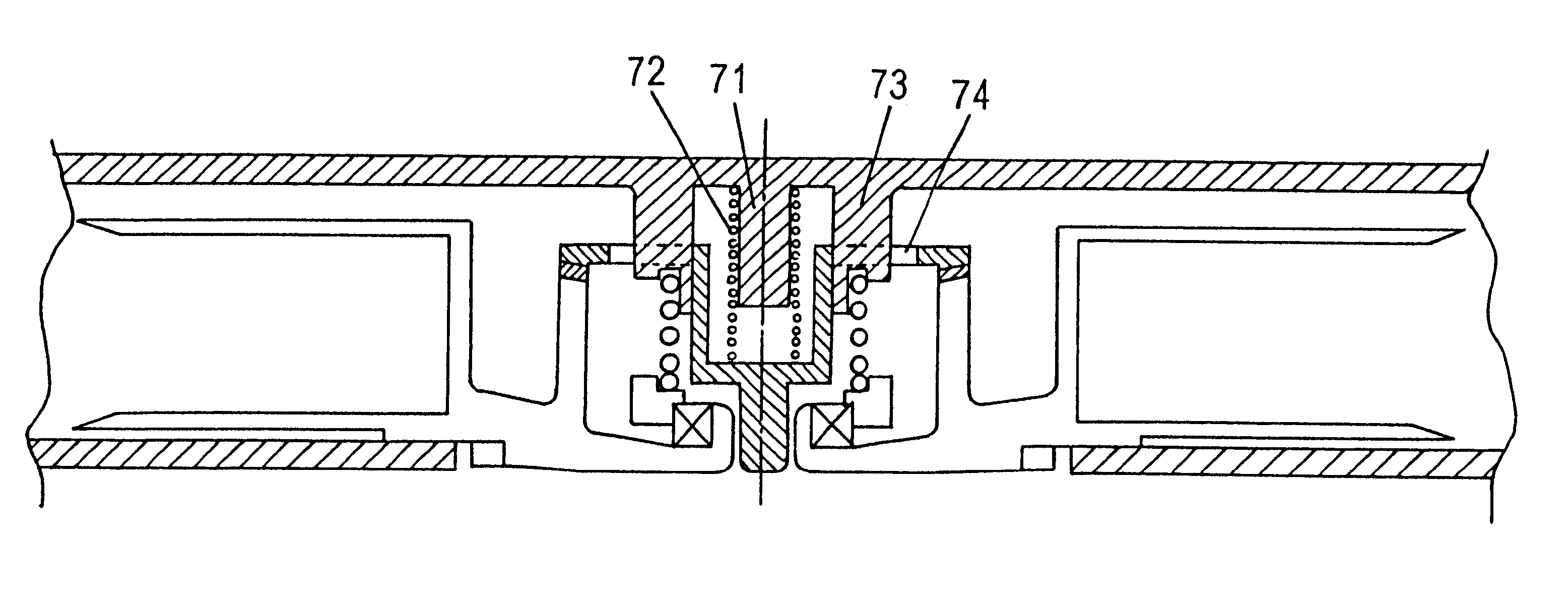
The present invention addresses and solves the problems of conventional tape cartridges stemming from the use of magnetic couplings for the supply reel and drive motor, and external reel locks which are actuated by separate mechanisms. External reel locks and magnetic couplings are both complex and unreliable. Furthermore, magnetic couplings subject the tape cartridge to undesirable impact forces. Still further, because external reel locks and magnetic couplings require separate actuation, they increase the complexity of the cartridge and the tape drive. The present invention provides simple and reliable reel lock and motor / reel coupling mechanisms whose functions are both accomplished during a single motion of the cartridge relative to the drive motor.

According to the present invention, the motor / reel coupling is accomplished by providing a circular set of gear teeth on the bottom of the tape reel which meshes with a complementary set of gear teeth on a motor coupling rotated by th...


PUM


Abstract

A tape cartridge is provided with reliable reel lock and motor/reel coupling mechanisms whose functions are both accomplished during a single motion of the cartridge relative to the drive motor. The motor/reel coupling includes a circular set of gear teeth on the bottom of the tape reel which meshes with a complementary set of gear teeth on a motor coupling rotated by the motor when the cartridge is loaded into the tape drive and the cartridge and motor are moved towards each other. An engagement force to maintain the coupling is provided by an engagement spring in the cartridge which biases the reel towards the motor. Reel locking is accomplished by providing a second circular set of gear teeth on a top side of the tape reel which meshes with a complementary set of gear teeth provided on a slidably mounted locking bracket inside the tape cartridge. A lock spring normally biases the locking bracket towards the top of the tape reel, thus locking the reel when the cartridge is not engaged with the motor. When the cartridge and the drive motor are moved towards each other, the motor coupling engages the bottom of the tape reel, and a projection on the motor coupling extends into the tape cartridge to slide the locking bracket out of engagement with the teeth on the top of the tape reel, thereby unlocking the reel. Thus, reel unlocking and motor/reel coupling are accomplished with a single motion by reliable mechanisms.

Description

FIELD OF THE INVENTIONThe present invention relates to a cartridge for tape media stored on a reel. The invention has particular applicability to tape cartridges which require reel locks to prevent the tape from unraveling, and coupling engagement mechanisms for coupling the tape reel to a drive motor.BACKGROUND ARTCurrent demands for high-density data storage and high performance and reliability require tape handling systems which store as much tape as possible on a single supply reel in a cartridge. Such demands for increased density, performance and reliability require cartridges which are as simple and rugged as possible.Certain conventional tape drives, referring to FIG. 1, comprise a modular data cartridge 1 having a supply reel 2. The cartridge 1 is inserted into the tape drive through a front bezel 3, then the tape 4 is pulled out of the cartridge 1 and fed past a magnetic read / write head 5 and wound onto a take up reel 6, which is not removable from the tape drive. Upon rew...

Claims


Application Information

Patent Timeline
IPC IPC(8): G11B23/107G11B23/04G11B15/32G11B23/08G11B15/26
CPCG11B15/32G11B23/043G11B23/107
Inventor NAYAK, ASHOK B.
Owner QUANTUM CORP
Why Eureka
Try Eureka