Retractable oven rack assembly

Inactive Publication Date: 2006-05-18
BSH HOME APPLIANCES CORP
View PDF14 Cites 45 Cited by
  • Summary
  • Abstract
  • Description
  • Claims
  • Application Information

AI Technical Summary

Benefits of technology

[0011] In a more specific aspect, one of the first two wire sections includes a raised section at the rear of the wire base to form respective first stops at the connections between the wire section of the first two wire sections at the rear, and the second two wire sections. The other end of the first two wire sections includes a raised section at the front of the of the wire base to f

Problems solved by technology

In these types of arrangements, due to the fact that the oven rack must be supported over a substantial portion thereof by the support slots or ledges of the oven cavity walls, the amount which the rack can be extended out of the oven cavity is limited.
This results in difficulty in positioning food items on such racks or in removing the food items from the rack.
This also creates a danger that the person removing or replacing such items on the rack may inadvertently contact the hot walls of the oven cavity.
While desirable from the perspective of allowing greater extension of the oven rack out of the cavity of the oven, this type of arrangement takes up a substantial amount of additional space within an oven cavity due to the fact that it is essentially a double rack arrangement, with each rack separated from

Method used


Image

  • Retractable oven rack assembly
  • Retractable oven rack assembly
  • Retractable oven rack assembly

Examples


Embodiment Construction

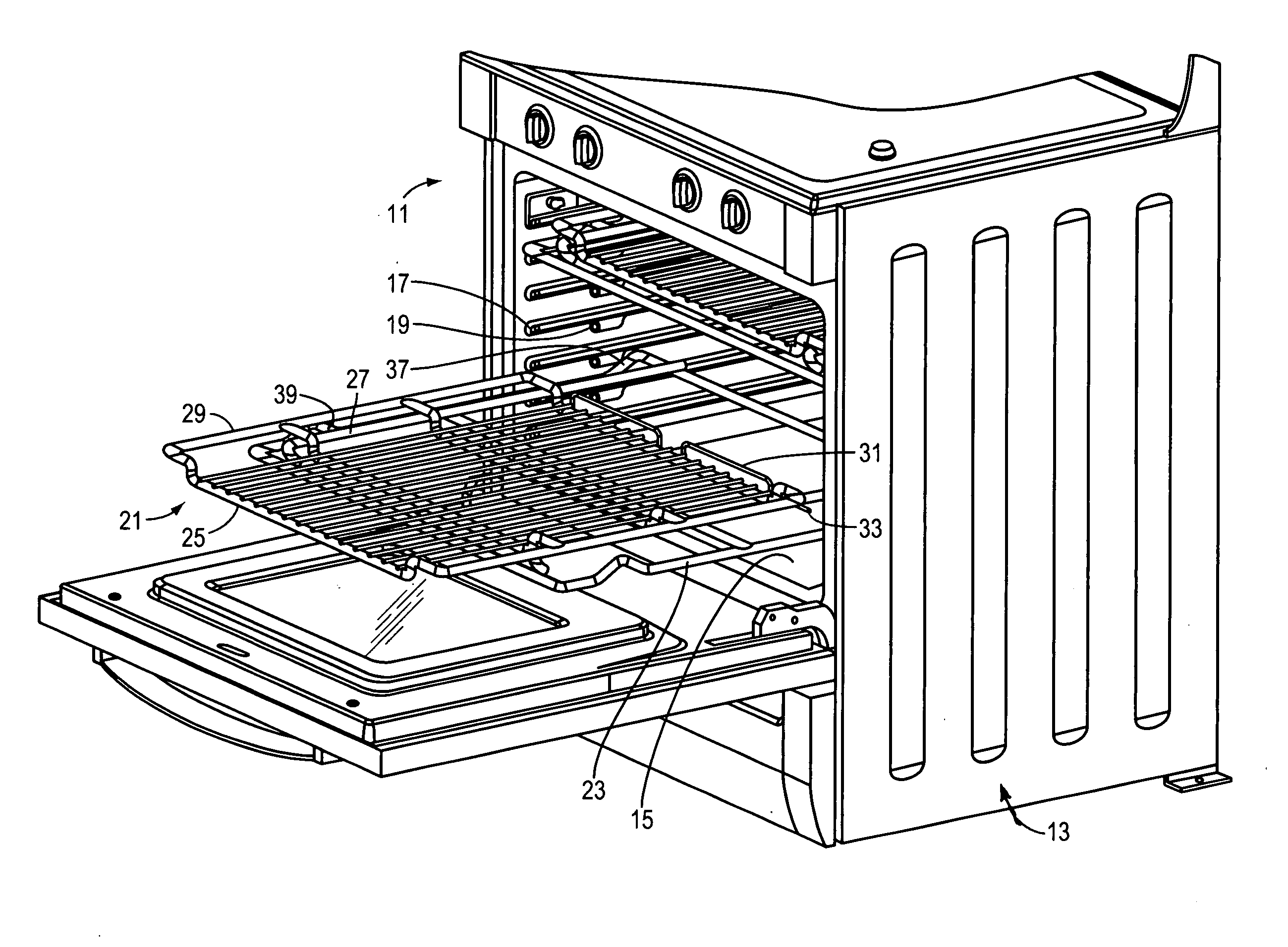
[0022]FIG. 1 is a perspective view of the oven rack system 11 in accordance with the present invention. An oven 13 includes an oven cavity 15 and oven rack support, here a plurality of shelves 17, with the respective parallel opposite shelves not shown. The shelves 17 each include a shelf stop 19, which serves to limit the movement of an oven rack outwardly from the cavity 15 and into the oven cavity 15.

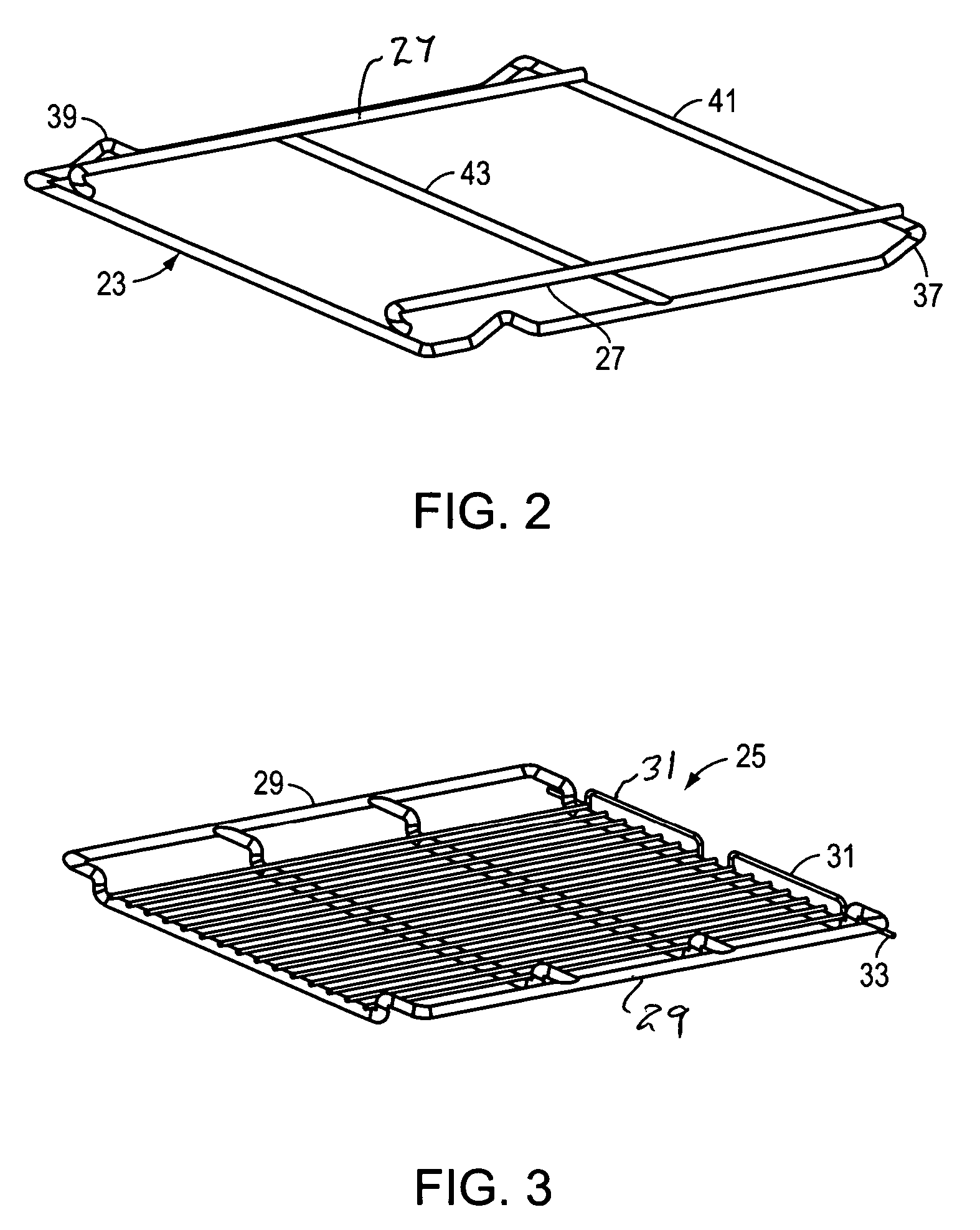
[0023] A retractable oven rack 21 in accordance with the present invention includes two separate parts, a slidable wire base 23 and a grid shelf 25.

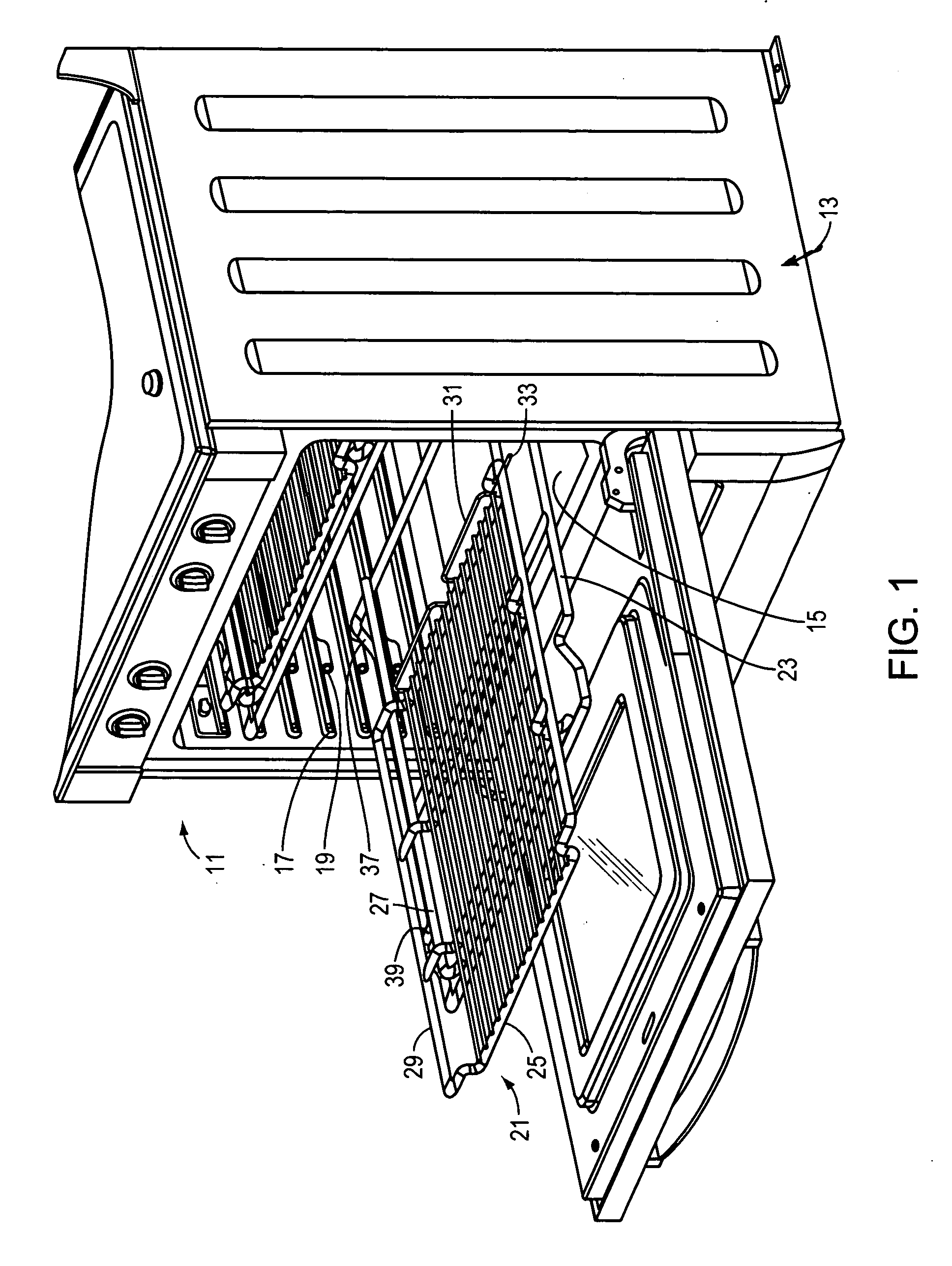
[0024] As shown in FIG. 2, the wire base 23 is made of four generally horizontally extending wire sections, two along the width and two along the length thereof. The wire base includes a pair of support rods 27 connected thereto and a strengthening rod 43 extending across the middle of the wire base 23 along the width thereof. A wire rod 41 is positioned at the rear, and makes up one of the two wire sections extending along the length o...


PUM


Abstract

A retractable oven rack is made up of two separate parts, a first part being a slidable wire base, which is rectangularly shaped and has four wire sections extending generally horizontally around the periphery thereof. Two of the wire sections extend parallel to each other along the width of the wire base and the other two extend parallel along the length. The four wires sections are connected to each other at the ends thereof. A pair of support rods are located from and extending respectively parallel to two of the wire sections along the length of the slidable wire base. The second part is a grid shelf having a pair of raised wire sections extending the length of the grid shelf located at a position for being slidably supported on the pair of support rods for allowing the grid shelf to be supported and slide on the pair of support rods.

Description

BACKGROUND OF THE INVENTION [0001] 1. Field of the Invention [0002] This invention relates to a retractable oven rack assembly for use in an oven. The invention also relates to a combination oven and retractable oven rack. More particularly, the invention relates to a retractable oven rack assembly made up of two parts, with a grid shelf supported on a slidable base which can be slid out of the oven, and the grid shelf is slidable on top of the base for being easily extended out of and retracted back into the oven cavity. [0003] 2. Discussion of the Prior Art [0004] In cooking appliances such as ovens or free standing ranges which include ovens, the oven cavity is typically populated with one or more racks to support food items being cooked in the oven. The oven cavities include support slots, racks or ledges in the side walls thereof which allow the oven racks to be slidably received and retained within the oven cavity. The support slots, racks or ledges also typically include an u...

Claims


Application Information

Patent Timeline
IPC IPC(8): A47J37/07
CPCF24C15/16
Inventor BAKER, EDWARDMAY, GEORGESAUNDERS, HOWARDSTAEBLER, MANFRED W.WHITEHEAD, DARON
Owner BSH HOME APPLIANCES CORP
Why Eureka
Try Eureka