Clip

Inactive Publication Date: 2006-05-18
NEWFREY
20 Cites 1 Cited by

AI-Extracted Technical Summary

Problems solved by technology

However, this clip does not sufficiently adapt to workpieces of varying thickness, and does not engage thin workpieces effectively.
However, such plate-shaped portions and play-preventing fingers require substantial mounting space on the workpiece.
As a result, t...

Method used

[0040] When fastening parts of the clip 1 together, the thin hinge 15 is turned around its center line. The first divided base portion 6A and the second divided base portion 6B are fastened together to form the base 6, and the first divided shank portion 7A and the second divided shank portion 7B are fastened together to form the shank 7. In this way, the fastening operation is simple. In order to keep the base 6 and the shank 7 on the clip 1 fastened together, a latch is formed on the first divided shank portion 7A and the second divided shank portion 7B. The latch comprises a protrusion 17 and a recess 18 on the first divided shank portion 7A and the second divided shank portion 7B. Two pairs of protrusions 17 and recesses 18 can be formed to hold parts of the clip together. FIG. 12 shows each protrusion 17 engaging a corresponding recess 18 to keep the clip fastened. When the divided base 6 and shank 7 are turned around the thin hinge 15 to fasten them together and another component such as a strap 2 (see FIG. 13) is attached to the base 6, the other component is preferably attached to the base 6 before the clip is fastened. The clip is then fastened and mounted. This makes the mounting process easier.
[0042] If semicircular recesses 19A, 21A are formed in the first divided base portion 6A and semicircular recesses 19B, 21B are formed in the s...

Benefits of technology

[0009] An object of the present invention is to provide an improved clip t...

Abstract

A clip 1 comprises a base 6, a shank 7 extending from the base 6, a pair of legs 9A, 9B extending from an end of the shank towards the base and away from a side of the shank, and a pair of elastic fingers 11A, 11B extending from the end of the shank towards the base and away from a side of the shank, juxtaposed with the legs. A curved end 12 is formed at the end of each finger to engage the edge of a mounting hole 5 in a workpiece. Complementary parts of a molded plastic clip, connected by a hinge, are fastened to one another before mounting of the clip.

Application Domain

Snap fastenersSnap-action fasteners +9

Technology Topic

Hinge angleMechanical engineering

Image

  • Clip
  • Clip
  • Clip

Examples

  • Experimental program(1)

Example

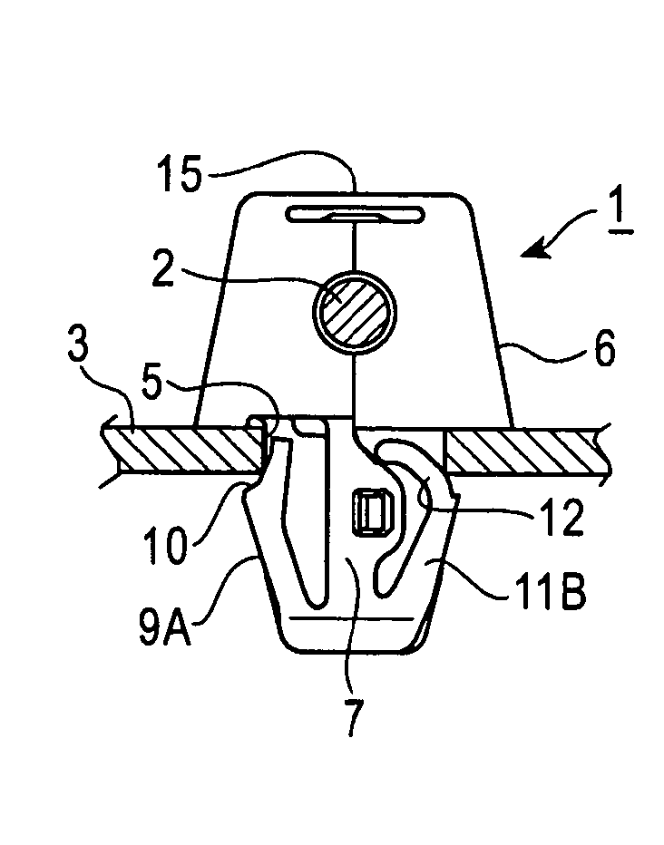
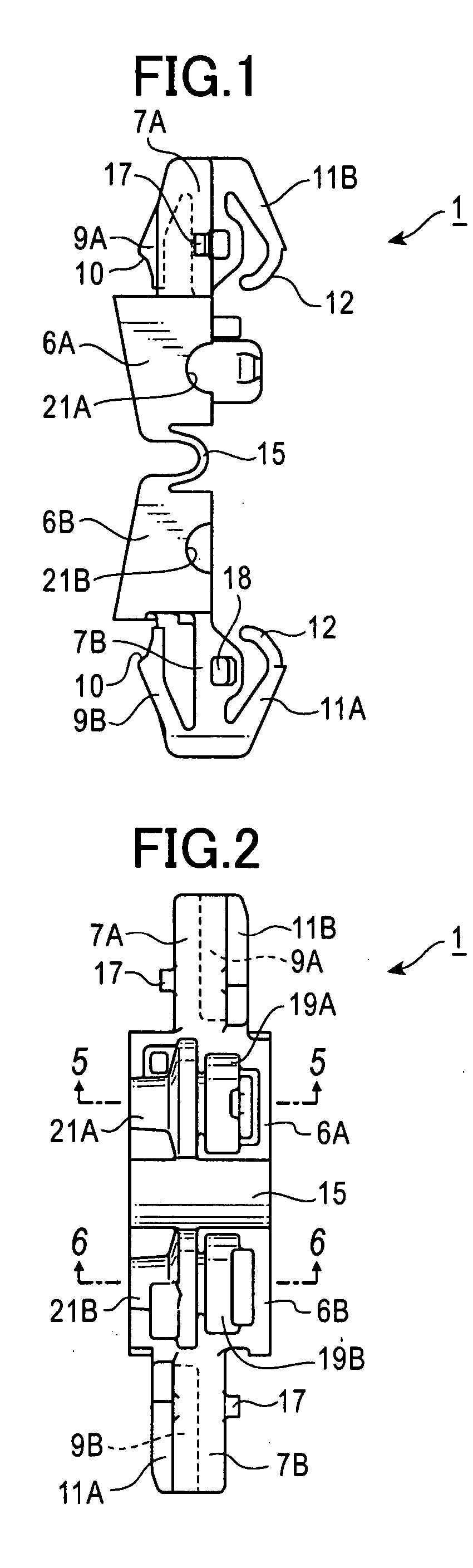
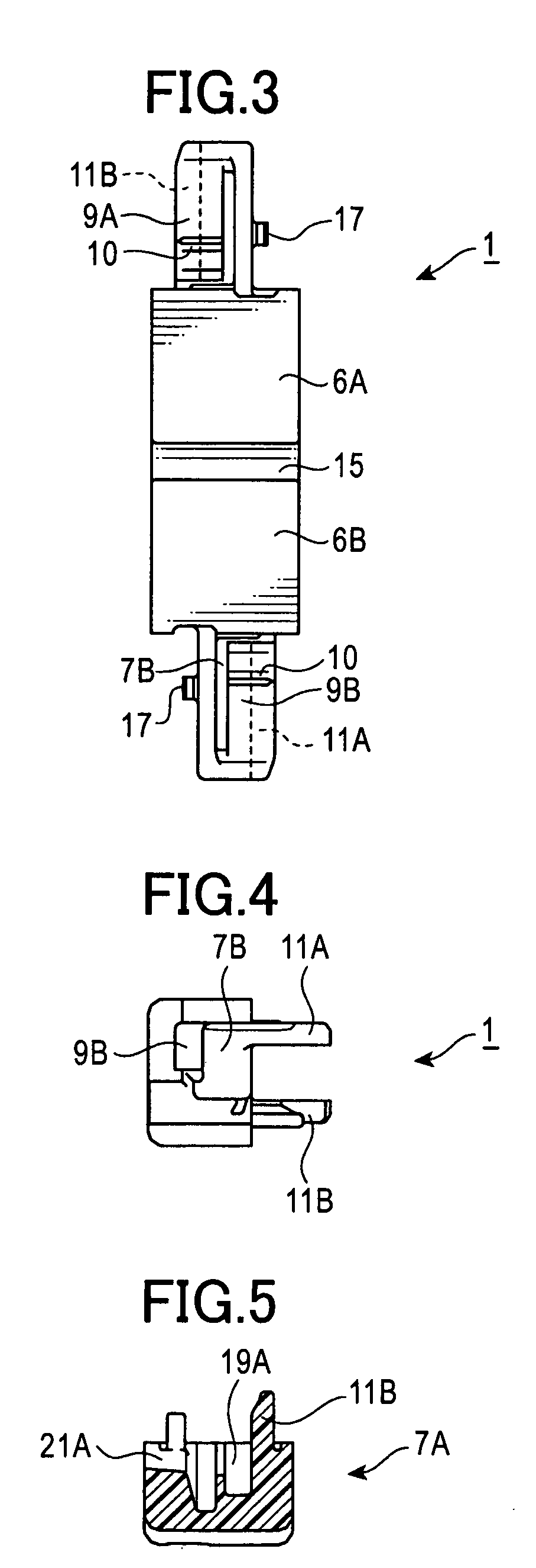
[0034] The following is an explanation of a clip in an embodiment of the present invention with reference to the drawings. FIGS. 1-6 show the clip 1 before complementary parts thereof are fastened together, and FIGS. 7-12 show the clip 1 after the parts are fastened together. FIGS. 13-15 show the clip 1 mounted in a mounting hole 5 in a workpiece 3 such as a car body to fasten an end of a strap 2 extending from a fuel cap. FIG. 16 and FIG. 17 show the action of the fingers (described below) on the clip 1 when mounted to workpieces of different thicknesses. In this embodiment, as shown in FIG. 1 through FIG. 6, the clip 1 is divided in two vertically to form two portions during molding, and parts remain unfastened from one another before use. Complementary parts of the clip 1 are fastened together only when it is mounted on the workpiece 3 as shown in FIG. 7 through FIG. 12. The clip 1 shown in FIG. 13 through FIG. 15, holds the end of a strap 2, and is mounted in the mounting hole 5 on the workpiece 3 while holding the strap 2.
[0035] The following is an explanation with reference to FIG. 7 through FIG. 9 of the clip 1, before its complementary parts are fastened together as shown in FIG. 1 through FIG. 6, and after its complementary parts are fastened together as shown in FIG. 7 through FIG. 12. As shown in FIG. 1, clip 1 is preferably an integral elongated molded product made of hard plastic. As shown in FIG. 1 through FIG. 6, the clip 1 is molded so as to be divided into two complementary parts axially, and the two divided parts connect together at a base 6. As shown in FIG. 1 through FIG. 3, the split extends the entire length. The clip 1, as shown in FIG. 7 and FIG. 9, comprises the base 6, a shank 7 extending from the base 6, and a pair of elastic legs 9 extending from the end of a shank 7 towards the base and away from a side of the shank 7. In FIG. 1 through FIG. 6, the base 6 includes a first divided base portion 6A and a second divided base portion 6B. The shank 7 includes a first divided shank portion 7A extending from the first divided base portion 6A and a second divided shank portion 7B extending from the second divided base portion 6B. One of the legs 9 is a first leg 9A extending towards the first divided base portion 6A from the end of the first divided shank portion 7A and away from the side of the first divided shank portion 7A, and the other leg is a second leg 9B extending towards the second divided base portion 6B from the end of the second divided shank portion 7B and away from the side of the second divided shank portion 7B. A shoulder 10 is formed at the end of the legs 9A, 9B to engage the edge of a mounting hole in the workpiece.
[0036] The clip 1 also has a first elastic finger 11A as shown at the bottom of FIG. 1 extending from the end of the second divided shank portion 7B towards the second divided base portion 6B and away from the side of the second divided shank portion 7B (upward in FIG. 1) opposite the second leg 9B, and a second elastic finger 11B as shown at the top of FIG. 1 extending from the end of the first divided shank portion 7A towards the first divided base portion 6A and away from the side of the first divided shank portion 7A (downward in FIG. 1) opposite the first leg 9A.
[0037] The first finger 11A and the second finger 11B constitute a pair of fingers. After the divided portions are fastened together, as shown in FIG. 7 through FIG. 12, the length of the clip molding is reduced (Cf. FIG. 1). The first finger 11A then extends parallel to the first leg 9A towards the base 6 and away from the side of the shank 7, and the second finger 11B extends parallel to the second leg 9B towards the base 6 and away from the side of the shank 7. As shown in FIG. 9 (and FIG. 11), curved ends 12 are formed at the ends of the elastic fingers 11A, 11B that curve towards the second divided shank portion 7B underneath the base 6 towards the bottom of the base. In FIG. 1, the curved end 12 on elastic finger 11A curves upward in a convex shape towards the side of the second divided shank portion 7B, and the curved end 12 on the elastic finger 11B curves downward in a convex shape towards the side of the first divided shank portion 7A. The curved ends 12 have a portion that engages the edge of a mounting hole in the workpiece. When engaging the edge of the mounting hole in the workpiece, their shape and elasticity produce a rebounding force that separates them from the base 6 and the shank 7 regardless of the thickness of the workpiece. This rebounding force is able to prevent play of base 6 and shank 7 with respect to the workpiece regardless of the thickness of the workpiece.
[0038] After parts of the clip 1 have been fastened together, as shown in FIG. 7 and FIG. 8, the first leg 9A and the second leg 9B oppose each other with the shank 7 in the center, and the first finger 11A and the second finger 11B oppose each other with the shank 7 in the center. As shown in FIG. 8, a line joining the legs 9A, 9B intersects a line joining the fingers 11A, 11B at the shank 7. This distributes the retaining force of the legs 9A, 9B and the play-opposing force of the fingers 11A, 11B equally around the shank 7, and secures the clip 1 to the workpiece firmly without any play.
[0039] In the clip 1, the first divided shank portion 7A extends integrally from the first divided base portion 6A, the second divided shank portion 7B extends integrally from the second divided base portion 6B, and the first divided base portion 6A is connected to the second divided base portion 6B by a thin hinge 15. In this way, the entire clip 1 is integral. The first divided shank portion 7A, the first divided base portion 6A, the thin hinge 15, the second divided base portion 6B and the second divided shank portion 7B all extend lengthwise. By connecting the first divided base portion 6A and the second divided base portion 6B divided down the center lengthwise with a thin hinge 15, the intricate internal shape of the base 6 and shank 7 are exposed. This makes the mold for the clip 1 simpler.
[0040] When fastening parts of the clip 1 together, the thin hinge 15 is turned around its center line. The first divided base portion 6A and the second divided base portion 6B are fastened together to form the base 6, and the first divided shank portion 7A and the second divided shank portion 7B are fastened together to form the shank 7. In this way, the fastening operation is simple. In order to keep the base 6 and the shank 7 on the clip 1 fastened together, a latch is formed on the first divided shank portion 7A and the second divided shank portion 7B. The latch comprises a protrusion 17 and a recess 18 on the first divided shank portion 7A and the second divided shank portion 7B. Two pairs of protrusions 17 and recesses 18 can be formed to hold parts of the clip together. FIG. 12 shows each protrusion 17 engaging a corresponding recess 18 to keep the clip fastened. When the divided base 6 and shank 7 are turned around the thin hinge 15 to fasten them together and another component such as a strap 2 (see FIG. 13) is attached to the base 6, the other component is preferably attached to the base 6 before the clip is fastened. The clip is then fastened and mounted. This makes the mounting process easier.
[0041] The base 6 in this clip 1 can include a holder for holding the connected end of a strap 2 extending from a fuel cap (not shown). The holder comprises semicircular recesses 19A, 19B and semicircular recesses 21A, 21B with a smaller diameter than the semicircular recesses 19A, 19B formed in the first divided base portion 6A and the second divided base portion 6B (FIG. 1, FIG. 2, FIG. 5, FIG. 6). The connected end of the strap 2 is housed in the semicircular recesses 19A, 19B, and the strap 2 extends from the smaller-diameter semicircular recesses 21A, 21B. In this way, the clip 1 can be used to mount a fuel cap on a part of a car body such as a panel (workpiece) without having to form a special engagement portion.
[0042] If semicircular recesses 19A, 21A are formed in the first divided base portion 6A and semicircular recesses 19B, 21B are formed in the second divided base portion 6B to form the connector for the strap 2 as shown in FIG. 13, and if the first divided base portion 6A and the second divided base portion 6B are fastened together, the strap 2 can be held by the base 6 after it is fastened together. This makes the holding operation simpler.
[0043] After it has been fastened, the clip 1 comprises the base 6, the shank 7 extending from the base 6, the pair of legs 9A, 9B extending from the end of the shank 7 towards the base 6 and away from a side of the shank 7, and the pair of elastic fingers 11A, 11B extending from the end of the shank 7 towards the base 6 and away from a side of the shank 7, juxtaposed with the legs 8A, 9B. A curved end 12 is formed at the end of the fingers 11A and 11B to engage the edge of the mounting hole 5 in the workpiece. The curved end 12 is curved along the underside of the base 6 towards a side of the shank 7. When the curved end 12 is engaged with the edge of the mounting hole, it has a rebounding force that separates it from the base 6 and the shank 7 regardless of the thickness of the workpiece. The rebounding force from the curved end 12 of the fingers 11A and 11B keeps the base 6 and shank 7 attached to the workpiece without play, regardless of the thickness of the workpiece. The legs 9A and 9B also have shoulders 10. When the shank 7 and the legs 9A and 9B are inserted into the mounting hole in the workpiece, the shoulders 10 engage the edge of the mounting hole and the workpiece is mounted. The clip 1 is mounted to the workpiece in this way.
[0044] In FIG. 13 through FIG. 15, the end of a strap 2 extending from a fuel cap is held by the base 6, and the clip 1 is mounted on a workpiece 3 such as a panel on a car body. When the first divided base portion 6A and the second divided base portion 6B are fastened together to form the base 6, the recesses 19A, 19B, 21A, 21B (FIG. 9 and FIG. 10) are fastened together to form a holder in the base 6 for the end of the strap 2. The legs 9A, 9B are inserted into the mounting hole 5 in the workpiece 3, the shoulders 10 engage the edge of the mounting hole 5, the clip 1 is mounted on the workpiece and, thus, the strap 2 is mounted on the workpiece 3.
[0045] As shown in FIG. 14 and FIG. 15, the curved ends 12 of the fingers 11A, 11B engage the edge of the mounted hole 5. The shape and elasticity of the curved ends 12 produce a rebounding force that separates them from the bottom surface of the base 6 and the side surface of the shank 7. The fingers themselves are attached to the mounting hole 5, and the rebounding force of the curved ends 12 is able to prevent play of base 6 and shank 7 with respect to the workpiece regardless of the thickness of the workpiece.
[0046]FIG. 14, FIG. 16 and FIG. 17 show clips 1 mounted on workpieces 3, 3A, 3B of varying thicknesses. The workpiece 3A in FIG. 16 is thinner than the workpiece 3 in FIG. 14, and the workpiece 3B in FIG. 17 is thicker than the workpiece 3 in FIG. 14. As shown in the drawings, the leg 9A has a shoulder 10 that engages the edge of the mounting holes 5 in the workpieces 3, 3A, 3B. Finger 11B has a curved end 12 that engages the edge of the mounting holes 5 in the workpieces 3, 3A, 3B. Although not seen in the drawings, leg 9B and finger 11A engage the mounting holes 5 in a similar manner. The curved ends 12 engage the edge of the mounting hole 5 in a different position depending on the thickness of the workpiece 3, 3A, 3B. The rebounding force of the curved ends 12 applies and maintains strong pressure against the edge of the mounting hole 5.
[0047] As shown by arrow 22 in FIG. 16, the force applied and maintained on the edge of the mounting hole 5 when the clip 1 is mounted on a thin workpiece 3A is the same strength as the force applied and maintained on workpieces 3, 3B with different thicknesses (FIG. 14 and FIG. 17). Whether the workpiece is thick or thin, the curved ends 12 reliably make contact with the edge of the mounting hole and the rebounding force separates them from the bottom surface of the base 6 and the side surface of the shank 7. As a result, the fingers 11A, 11B prevent play by the base 6 and shank 7 against the workpiece regardless of the thickness of the workpiece.
[0048] As mentioned above, the curved ends 12 of the fingers 11A, 11B strongly engage the edge of the mounting hole 5 and the fingers themselves fix the clip 1 to the workpiece, so that the rebounding force from the fingers prevents play of the base 6 and shank 7 against the workpiece regardless of the thickness of the workpiece. The prevention of play also prevents random noise, keeps the clip mounted on the workpiece properly, stabilizes the legs inside the mounting hole, and keeps the legs from coming out of the workpiece. It also maintains the strong force of the legs 9A, 9B, and secures the clip 1 to the workpiece. The curved ends 12 absorb the difference in workpiece thickness on the back side and not the front side of the workpiece 3, 3A, 3B. As a result, the appearance of the workpiece is not compromised. As a result, the base 6 does not require an elastic absorption plate, and the base 6 or shank 7 does not require play-preventing fingers. This reduces the mounting area on the workpiece and allows the clip to be attached in narrow confines.
[0049] While a preferred embodiment of the invention has been shown and described, changes can be made without departing from the principles and spirit of the invention, the scope of which is defined in the following claims.

PUM

no PUM

Description & Claims & Application Information

We can also present the details of the Description, Claims and Application information to help users get a comprehensive understanding of the technical details of the patent, such as background art, summary of invention, brief description of drawings, description of embodiments, and other original content. On the other hand, users can also determine the specific scope of protection of the technology through the list of claims; as well as understand the changes in the life cycle of the technology with the presentation of the patent timeline. Login to view more.
Why Eureka
Try Eureka