MEMS-based sensor for lubricant analysis

a sensor and lubricant technology, applied in the field of apparatus and methods for analyzing fluids, can solve the problems of unnecessary or accelerated wear of lubricated components, sensor is large and bulky, and it is difficult to move from machine to machine to make fluid contamination measurements

Inactive Publication Date: 2006-05-18
PREDICT
View PDF53 Cites 121 Cited by
  • Summary
  • Abstract
  • Description
  • Claims
  • Application Information

AI Technical Summary

Problems solved by technology

The presence of corrosive products, contaminants, metallic particles, oxidation, etc. in fluids, such as lubricants, can cause problems.
For example, contaminants in lubricants can lead to damage of machinery in which the lubricant is utilized, causing unnecessary or accelerated wear on the lubricated members.
However, this solution suffers from a drawback in that the sensor is large and bulky and is difficult to move from machine to machine to make fluid contamination measurements.
The system of U.S. Pat. No. 5,262,732 is also rather large and cumbersome and does not lend itself to portability.
In the field, it would be difficult to transport the device from machine to machine to analyze the lubricant at the location of the machinery, for example.
Unfortunately, in some machines, obtaining a manual fluid sample with a large, unwieldy sensor is inconvenient due to machine construction.
In some cases, prior art sensors are too large and unwieldy and do not conveniently affix to the machine without interfering with proper machine operation.
Prior to U.S. Pat. Nos. 4,047,814 and 5,504,573, this method relied upon a visual analysis of particulate distribution, which was a strong function of the technician's experience performing the analysis, thereby leading to inconsistent conclusions.
In addition, since the horizontal strip was removed for analysis, evaluation of the fluid at the machine site was difficult and, in many cases, impossible.
Although such a technique provides for an improvement in subsequent analysis conclusions, this technique does not overcome the requirement that an operator initially procure the sample and send it off-site for analysis.
The sample must still be removed for analysis which limits the locations in which such analysis materials may be located and, in some cases, prohibits their use altogether.
Further, if one wishes to affix the particulate distribution collection apparatus with its analysis equipment so that the horizontal strip need not be removed from the machine, the radiation source and photodetectors are undesirably large and thereby further limit the scope of their application.
The sensor disclosed in U.S. Pat. No. 6,204,656, however, determined the impedance of the fluid based on the magnitude of the impedance and contaminant selective materials were not thoroughly discussed.

Method used


Image

  • MEMS-based sensor for lubricant analysis
  • MEMS-based sensor for lubricant analysis
  • MEMS-based sensor for lubricant analysis

Examples


Embodiment Construction

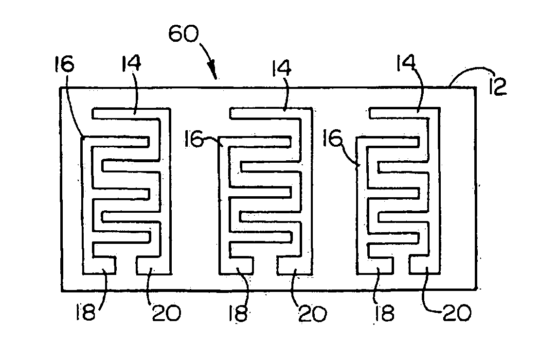
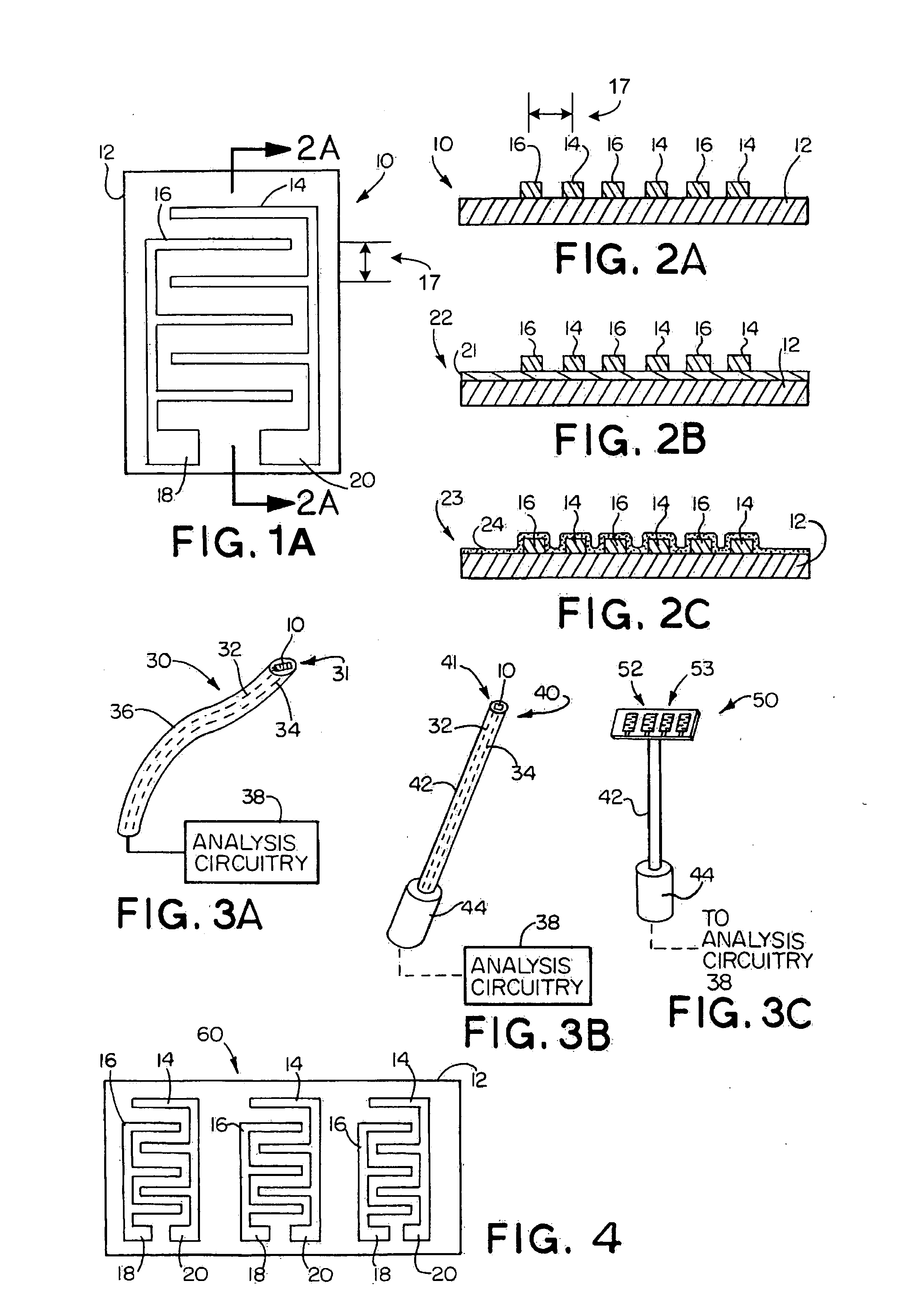
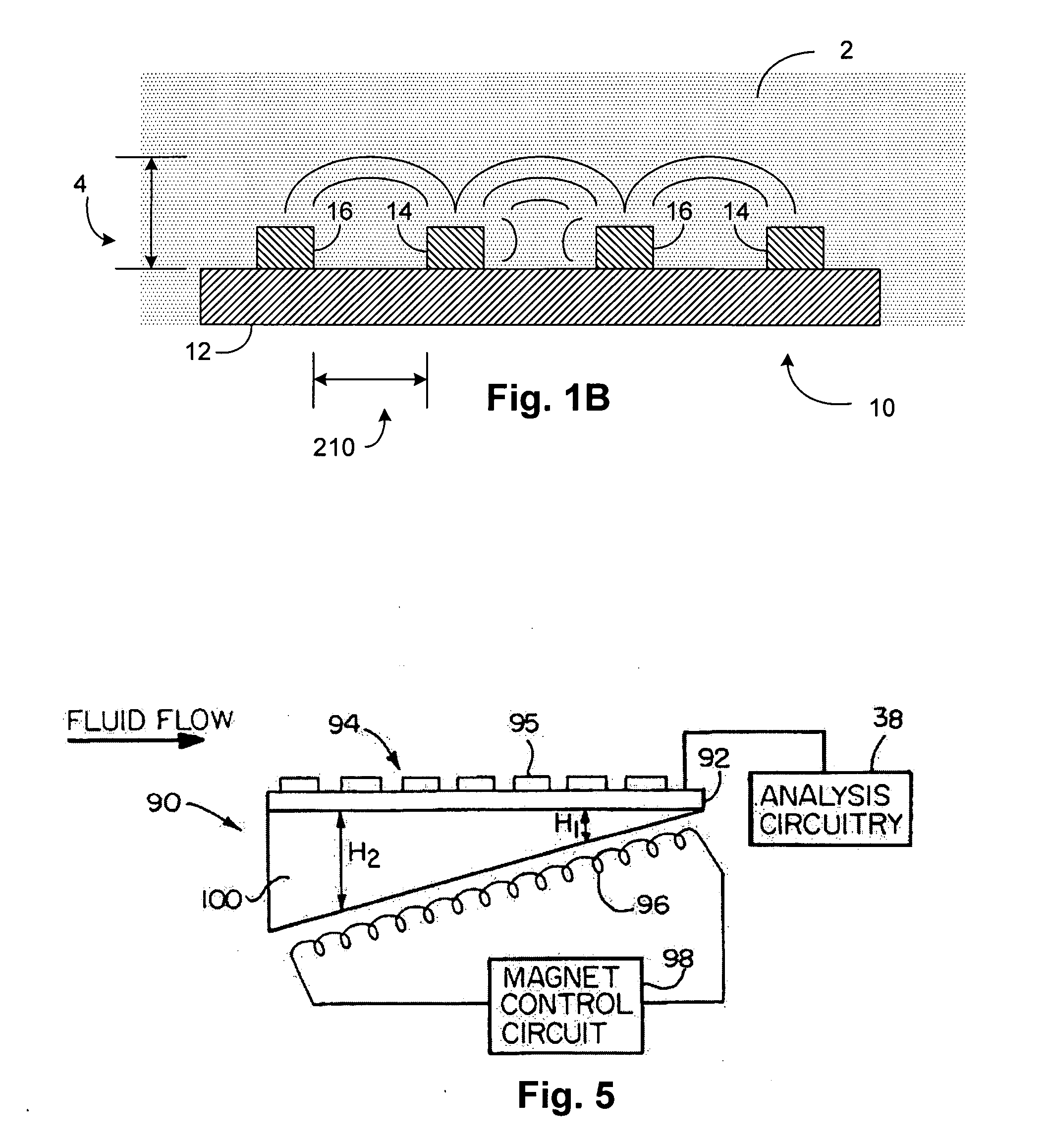
[0043] The present invention will now be described with reference to the drawings wherein like reference numerals are used to refer to like elements throughout. As will become more apparent based on the following description, a fluid contamination analyzer for monitoring contaminants in lubricating fluids utilizes micro-electromechanical (MEMS)-based sensors, thereby substantially reducing the sensor dimensions while providing a similar electrical response. This results in a greater variety of machine fluid analysis applications for the sensor. The MEMS-based sensor fabrication techniques also allow for a substantial reduction in sensor costs and provide high sensor manufacturability. Such fabrication techniques also allow for a substantial number of sensor variations with a sensor array for collecting a variety of types of data relating to fluid contamination.

[0044] Throughout the disclosure, reference will be made to impedance and impedance measurements. Impedance can be represen...


PUM

PropertyMeasurementUnit
thickaaaaaaaaaa
widthaaaaaaaaaa
thickaaaaaaaaaa

Abstract

A fluid contamination analyzer employs one or more MEMS-based sensors. The sensors are incorporated into probes or alternatively may be employed in an in-line analyzer residing in the fluid. The sensors, which can be selective to detect a distinct contaminant within the fluid, sense an impedance of the fluid, which is a function of its contamination and communicates the impedance to analysis circuitry.

Description

FIELD OF THE INVENTION [0001] The present invention relates generally to an apparatus and method for analyzing fluids such as lubricants. More particularly, the invention relates to a miniature sensor using micro-electromechanical (MEMS) device technology for detecting and monitoring conditions of a fluid, such as water content, oxidation and metallic or conductive particle contamination. BACKGROUND OF THE INVENTION [0002] The presence of corrosive products, contaminants, metallic particles, oxidation, etc. in fluids, such as lubricants, can cause problems. For example, contaminants in lubricants can lead to damage of machinery in which the lubricant is utilized, causing unnecessary or accelerated wear on the lubricated members. [0003] Various approaches have been developed to detect conditions involving deterioration and / or contaminants in fluids. One conventional system described in U.S. Pat. No. 4,646,070 utilizes a pair of capacitor electrodes positioned in a fluid. The fluid se...

Claims


Application Information

Patent Timeline
Patent Type & Authority Applications(United States)
IPC IPC(8): G01N27/02
CPCG01N27/126
Inventor NIKSA, ANDREW J.FOUSEK, JAMES D.
Owner PREDICT
Why Eureka
Try Eureka