Eureka AIR delivers breakthrough ideas for toughest innovation challenges, trusted by R&D personnel around the world.

Hinge

Inactive Publication Date: 2006-05-25
SUGATSUNE IND CO LTD
View PDF11 Cites 1 Cited by
  • Summary
  • Abstract
  • Description
  • Claims
  • Application Information

AI Technical Summary

Benefits of technology

[0005] This invention has been made in order to solve the above-mentioned problem. According to the present invention, there is provided a hinge comprising a hinge comprising a metal-made first hinge member including a first attachment plate part and a first cylindrical part disposed along one side part of the first attachment plate part with at least one part of the first cylindrical part projecting forward from a front surface of the first attachment plate part, a metal-made second hinge member including a second attachment plate part and a second cylindrical part disposed along one side part of the second attachment plate part with at least a part of the second cylindrical part projecting forward from a front surface of the second attachment plate part, a metal-made hinge pin inserted in the first and second cylindrical parts whose axes are aligned to each other and adapted to relatively turnably interconnect the first and second cylindrical parts, and a synthetic resin-made bush including an insertion cylindrical part inserted between an inner peripheral surface of the first cylindrical part and an outer peripheral surface of the hinge pin and movable with respect to at least one of the first cylindrical part and the hinge pin, and a flange part formed on one end part of the insertion cylindrical part in such a manner as to project radially outward therefrom and contacted with an end face of the first cylindrical part, the flange part being interposed between mutually opposing end faces of the first and second cylindrical parts, wherein a protection cylindrical part extending in the same direction as the insertion cylindrical part from the flange part and externally inserted to an outer peripheral surface of the first cylindrical part is integrally disposed at an outer peripheral part of the flange part, and the hinge further comprising a synthetic resin-made second bush, the second bush including a second protection cylindrical part and a second flange part integrally disposed at one end part of the second protection cylindrical part and projecting radially inward of the second protection cylindrical part, the second protection cylindrical part being externally inserted to the second cylindrical part, the second flange part being contacted with the end face of the second cylindrical part, the opposing end faces of the first and second cylindrical parts with the second flange part disposed therebetween being press-contacted with each other through the flange part and the second flange part.

Problems solved by technology

In the above-mentioned conventional hinge, however, no consideration is paid to metal powder dust at all which will be generated when the first and second cylindrical parts are accidentally collided with other metal-made member(s).
Owing to this arrangement, there is such a fear that goods under transportation are collided with the outer peripheral surfaces of the first and second cylindrical parts or those outer surfaces are rubbed with the goods under transportation.
In case the goods are made of metal or other hard material, there is such a fear that metal powder dust is generated from the outer peripheral surfaces of the first and second cylindrical parts.

Method used


Image

  • Hinge
  • Hinge
  • Hinge

Examples


first embodiment

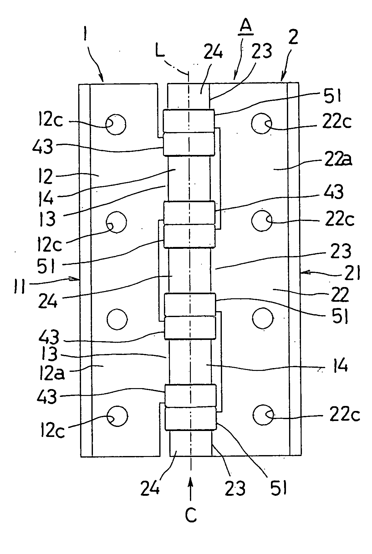
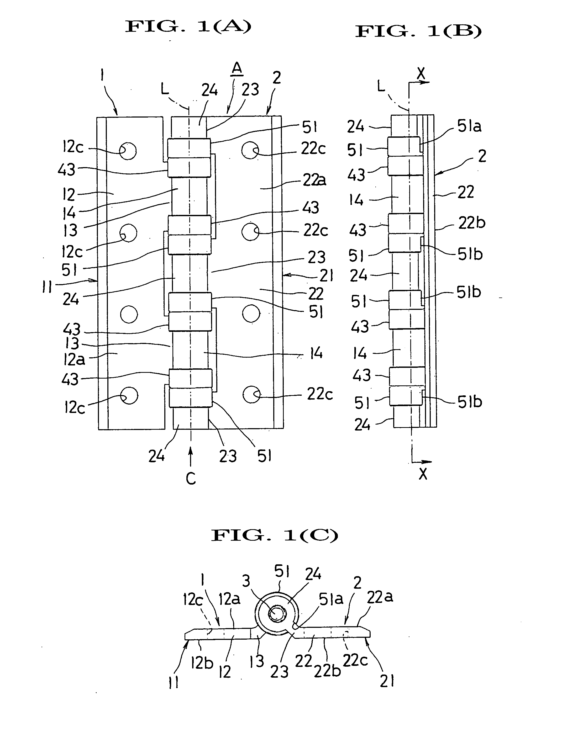
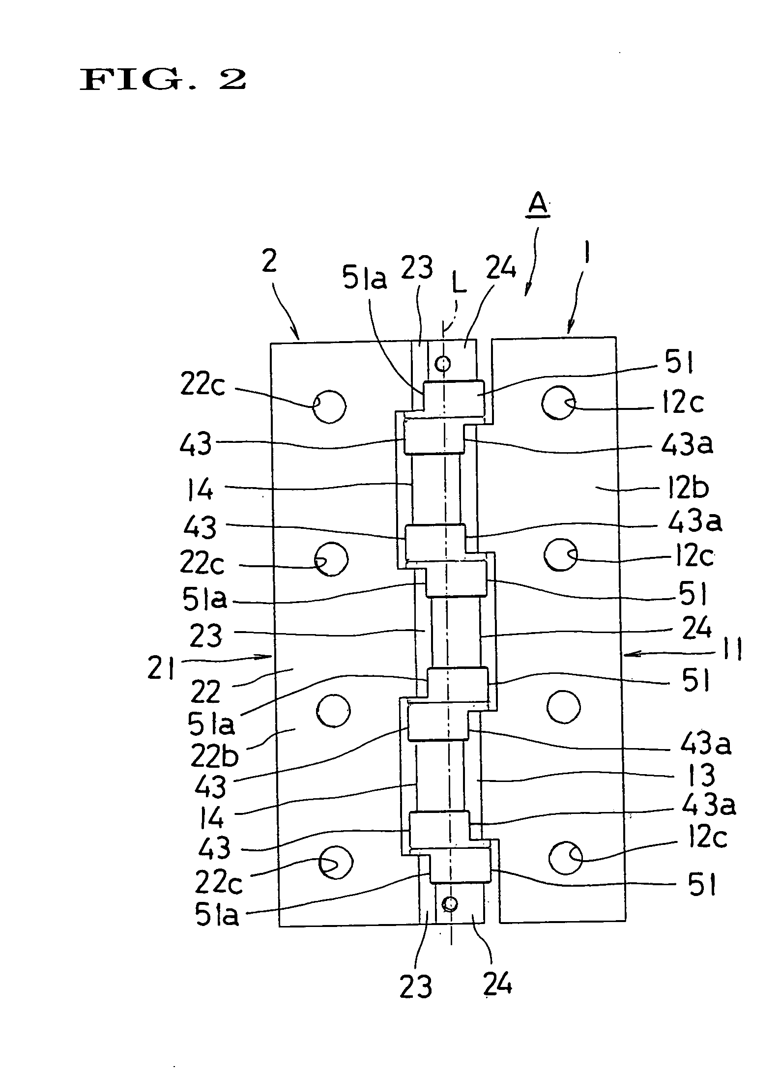
[0020]FIGS. 1 through 5 show the present invention. A hinge A according to this embodiment comprises a first hinge member 1, a second hinge member 2, a hinge pin 3, a first bush (bush) 4 and a second bush 5.

[0021] The first hinge member 1 is entirely made of metal such as aluminum. The first hinge member 1 includes a first attachment plate part 11. This first attachment plate part 11 comprises a flat plate part 12 having a rectangular configuration in a plan view, and a connecting plate part 13 connected to one side part along the longitudinal direction of the flat plate part 12 and projecting slantwise forward from the flat plate part 12. An attachment hole 12c is formed in the flat plate part 12 in such a manner as to pass through the back surface 12b from the front surface 12a. A machine screw (not shown) inserted in this attachment hole 12c is threadingly engaged with a skeleton or door (none of them is shown) and tightened, thereby the back surface 12b of the flat part 12 is ur...

second embodiment

[0037]FIGS. 6 through 9 show the present invention. In a hinge B according to this embodiment, the inside diameter of the second cylindrical part 24 is set to be equal to the inside diameter of the first cylindrical part 14. As a result, an annular space S′ having the same sectional configuration and sectional dimension as those of the space S formed between the inner peripheral surface of the first cylindrical part 14 and the outer peripheral surface of the hinge pin 3 is formed between the inner peripheral surface of the second cylindrical part 24 and the outer peripheral surface of the hinge pin 3.

[0038] A second insertion cylindrical part 53 extending in the same direction as a second protection cylindrical part 51 with its axis aligned with that of the second protection cylindrical part 51 is formed at the inner peripheral part of a second flange part 52 of a second bush 5. The second insertion cylindrical part 53 has the same sectional configuration and sectional dimension as ...

third embodiment

[0040]FIG. 10 shows the present invention. In this embodiment, the inner peripheral surface of a first cylindrical part 14 is formed in a regular square configuration in section. In accordance with the configuration of the first cylindrical part 14, the outer peripheral surface of an insertion cylindrical part 41 of a first bush 4 which is fitted to the first cylindrical part 14 is also formed in a regular square configuration in section. The inner peripheral surface of a second cylindrical part 24 and the outer peripheral surface of a second insertion cylindrical part53 of a second bush 5 which is fitted to the second cylindrical part 24 are also formed in a regular square configuration in section. The remaining construction is same as the hinge B.

INDUSTRIAL APPLICABILITY

[0041] A hinge according to the present invention can be utilized as a hinge for openably / closably and turnably attaching a door for opening / closing an entrance / exit of a clean room, or the like to a skeleton.


PUM


Abstract

A first bush is attached to each of the opposite end parts of a first cylindrical part of a first hinge member. Second bushes are attached respectively to the inner end parts of second cylindrical parts which are disposed at the opposite end parts of a second hinge member and to the opposite end parts of a second cylindrical part which is disposed at the central part of the second hinge member. The first bush is provided with a protection cylindrical part. This protection cylindrical part is fitted to the outer periphery of the first cylindrical part. The second bush is provided with a second protection cylindrical part. This second protection cylindrical part is fitted to the outer periphery of the second cylindrical part.

Description

TECHNICAL FIELD [0001] This invention relates to a hinge which is suited to be used in a clean room, etc. for manufacturing precise parts. BACKGROUND ART [0002] In general, a hinge of this type, as disclosed in Japanese Patent Application Laid-Open Application No. 2001-152727, comprises a first and a second hinge member which are made of metal, a bush which is made of synthetic resin and a hinge pin which is made of metal. The first and second hinge members include first and second planar attachment plate parts, and first and second cylindrical parts disposed at one side parts of the attachment plate parts, respectively. The first and second cylindrical parts are arranged with their axes aligned to each other. The bush includes an insertion cylindrical part and a flange part formed on one end part of the outer peripheral surface of the insertion cylindrical part. The insertion cylindrical part is inserted, for example, in the first cylindrical part. The flange part is sandwiched bet...

Claims


Application Information

Patent Timeline
IPC IPC(8): E05D7/00E05D5/14E05D5/10E05D9/00
CPCE05D5/10Y10T16/531Y10T16/537E05D5/14
Inventor YAMAGUCHI, KOSHI
Owner SUGATSUNE IND CO LTD
Why Eureka
Eureka Blog
Learn More