Generic rechargeable battery and charging system

Inactive Publication Date: 2006-05-25
CASTILLO HOMERO
View PDF14 Cites 47 Cited by
  • Summary
  • Abstract
  • Description
  • Claims
  • Application Information

AI Technical Summary

Benefits of technology

[0012] The present invention is an electrical energy storage device that includes a rechargeable element which stores electrical energy. A coil is inductively coupled to a source of electrical power. Control circuitry is integrated with the rechargeable element and the coil which controls a flow of electricity to the rechargeable element. The rechargeable device may be a standard size rechargeable battery. The energy storage device may have a size substantially the same as a standard size rechargeable battery. The coil is inductively coupled to the source of electrical power through a primary coil. The control circuitry comprises a rectifier and a current limiter.
[0013] Another embodiment of the present invention is a system for storage of electrical energy in a rechargeable element. A chamber has a primary coil coupled to a source of electrical power. The system includes a rechargeable battery that has a secondary coil and control circuitry integrated with the rechargeable element. With the rechargeable battery positioned inside the chamber, the secondary coil is inductively coupled to the primary coil. The rechargeable battery may be inside an appliance such as a camera, personal digital assistant, radio, shaver, toothbrush, beeper, cell phone, or a chemical sensor such as a H2S sensor. The source of electrical power may be an alternating current source. The source of electrical power may be a direct current source, in which case the system comprises a DC / AC converter.
[0014] In another embodiment, the invention is a method of storing electrical energy. A battery integrally comprised of (A) a secondary coil, (B) a rechargeable element, and, (C) control circuitry, are positioned in proximity to a primary coil. The primary coil is coupled to a source of electrical power, and electrical energy is stored in the rechargeable element. The battery may be positioned inside a chamber that includes the primary coil. The source of electrical power may be an alternating current source. In another embodiment, the source of electrical power may be a direct current source, in which case, the method further comprises a DC / AC converter.

Problems solved by technology

A disadvantage of this design is that as new batteries are developed for new or different portable computing devices, new battery chargers having slots that conform to the shape and electrode arrangement of the new batteries must be developed.
A drawback of the Toya device is that the secondary coil and the control circuitry for the battery pack are still external to the battery, and in a preferred embodiment, the battery pack is still appliance specific.

Method used


Image

  • Generic rechargeable battery and charging system
  • Generic rechargeable battery and charging system
  • Generic rechargeable battery and charging system

Examples


Embodiment Construction

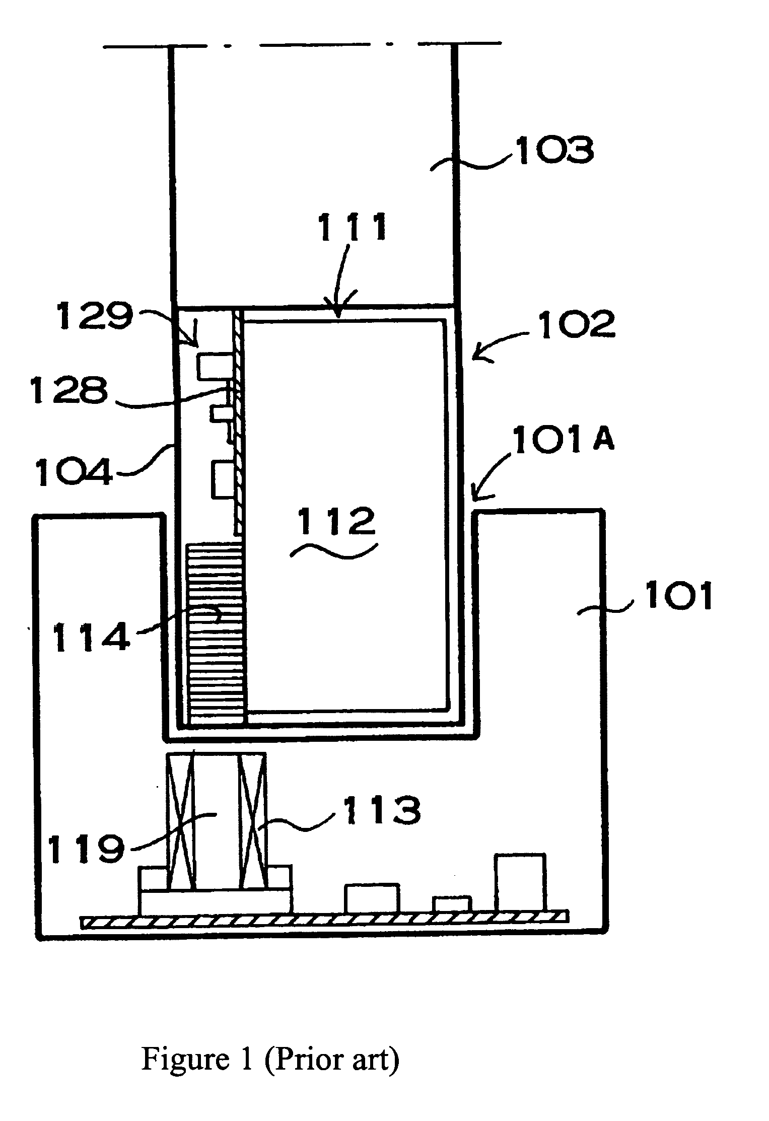
[0022]FIG. 1 (prior art) is a cross-sectional view in which a portable electrical device 103 is attached to the charging stand 101. The battery pack 102 shown in FIG. 1 comprises a cylindrically wound secondary coil 114. The secondary coil 114 is disposed at the bottom of the case 104 with its center axis oriented in the long direction of the case 104 and the battery, which is the vertical direction in FIG. 1. The case104 is rectangular shaped thin plastic and contains the rectangular rechargeable battery 111 inside thereof. The rectangular battery is thin and flat. The width of the rectangular case 104 is wider than the rectangular battery so that a gap is defined between the side of the rectangular case 104 and rectangular battery. The secondary coil 114 is disposed in the gap between the case 104 and the rechargeable battery 111. The secondary coil 114 is provided on the bottom surface of the case 104, and a printed circuit board (PCB) 128 is provided above the secondary coil 114...


PUM


Abstract

A rechargeable battery includes a rechargeable element, a transfer device and control circuitry. The transfer device may be a secondary coil with a corresponding primary coil that is supplied electrical power. The transfer device may be a photovoltaic cell supplied with light energy or a thermoelectric generator supplied with heat.

Description

BACKGROUND OF THE INVENTION [0001] 1. Field of the Invention [0002] The present invention is a rechargeable battery and a system for use in recharging the battery. [0003] 2. Background of the Art [0004] The prior art teaches various systems for charging a battery pack for use in a portable device. One such prior art system for computer devices includes a wall adapter unit connected by a cord to a battery charger. The battery charger contains one or more vertical slots in a top surface thereof in which battery packs are inserted for charging. Charging is achieved through direct electrical contact to external electrodes. A disadvantage of this design is that as new batteries are developed for new or different portable computing devices, new battery chargers having slots that conform to the shape and electrode arrangement of the new batteries must be developed. [0005] U.S. Pat. No. 5,734,254 to Stephens discloses a battery pack that comprises a battery mounted within a housing and coup...

Claims


Application Information

Patent Timeline
Patent Type & Authority Applications(United States)
IPC IPC(8): H02J7/00
CPCH02J7/025H02J7/35Y02E10/566Y02E10/56H02J50/10
Inventor CASTILLO, HOMERO
Owner CASTILLO HOMERO
Why Eureka
Try Eureka