Haptic feedback for button and scrolling action simulation in touch input devices

a technology of touch input device and haptic feedback, which is applied in the direction of instruments, computing, electric digital data processing, etc., can solve the problems of not including touchpads, requiring too large workspace for moving mouse-type position encoding input devices, and not providing haptic feedback to users, etc., to achieve enhanced interaction and manipulation

Active Publication Date: 2006-05-25
IMMERSION CORPORATION
View PDF98 Cites 357 Cited by
  • Summary
  • Abstract
  • Description
  • Claims
  • Application Information

AI Technical Summary

Benefits of technology

[0008] The present invention is directed to a haptic feedback planar touch input device used to provide input to a computer system. The touch input device can be a touchpad provided on a portable computer, or it can be a touch screen found on a variety of dev

Problems solved by technology

In portable computer or electronic devices, such as laptop computers, moveable mouse-type position encoding input device often require too large a workspace to be practical.
Touchpads do not incorporate an integral display device—touchscreens do.
One problem with existing touch input devices is that there is no haptic feedback pro

Method used


Image

  • Haptic feedback for button and scrolling action simulation in touch input devices
  • Haptic feedback for button and scrolling action simulation in touch input devices
  • Haptic feedback for button and scrolling action simulation in touch input devices

Examples


Embodiment Construction

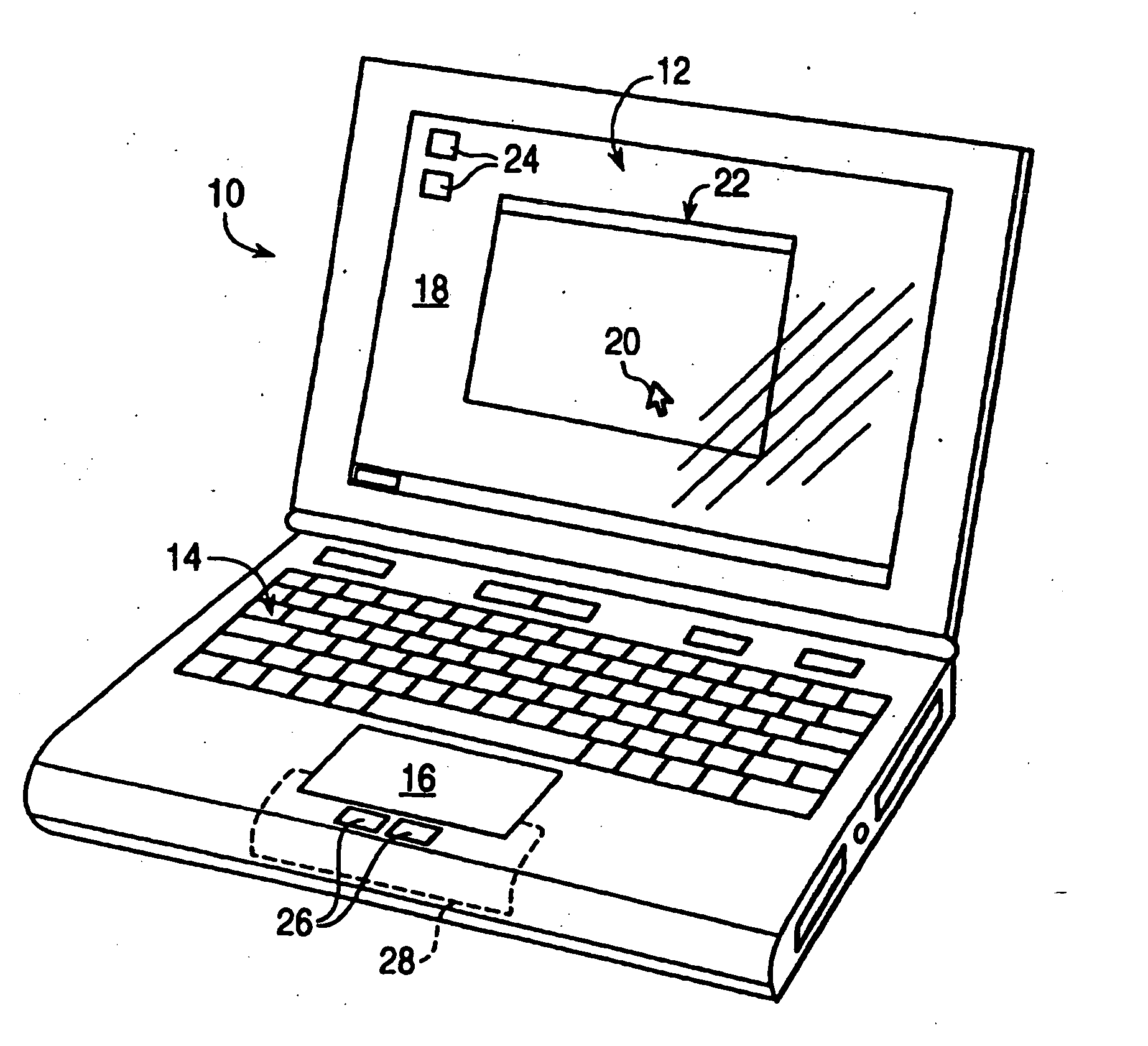
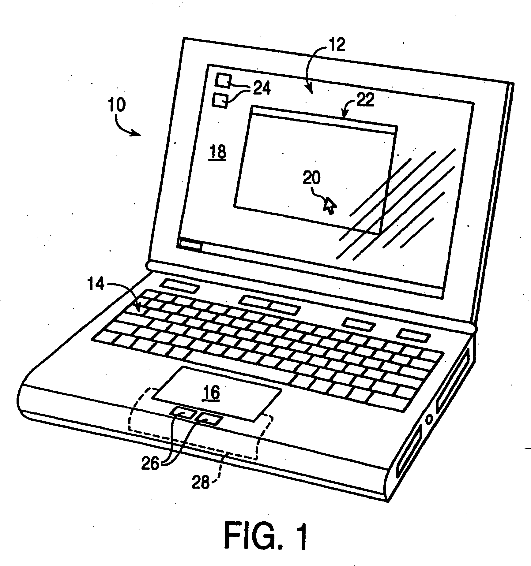
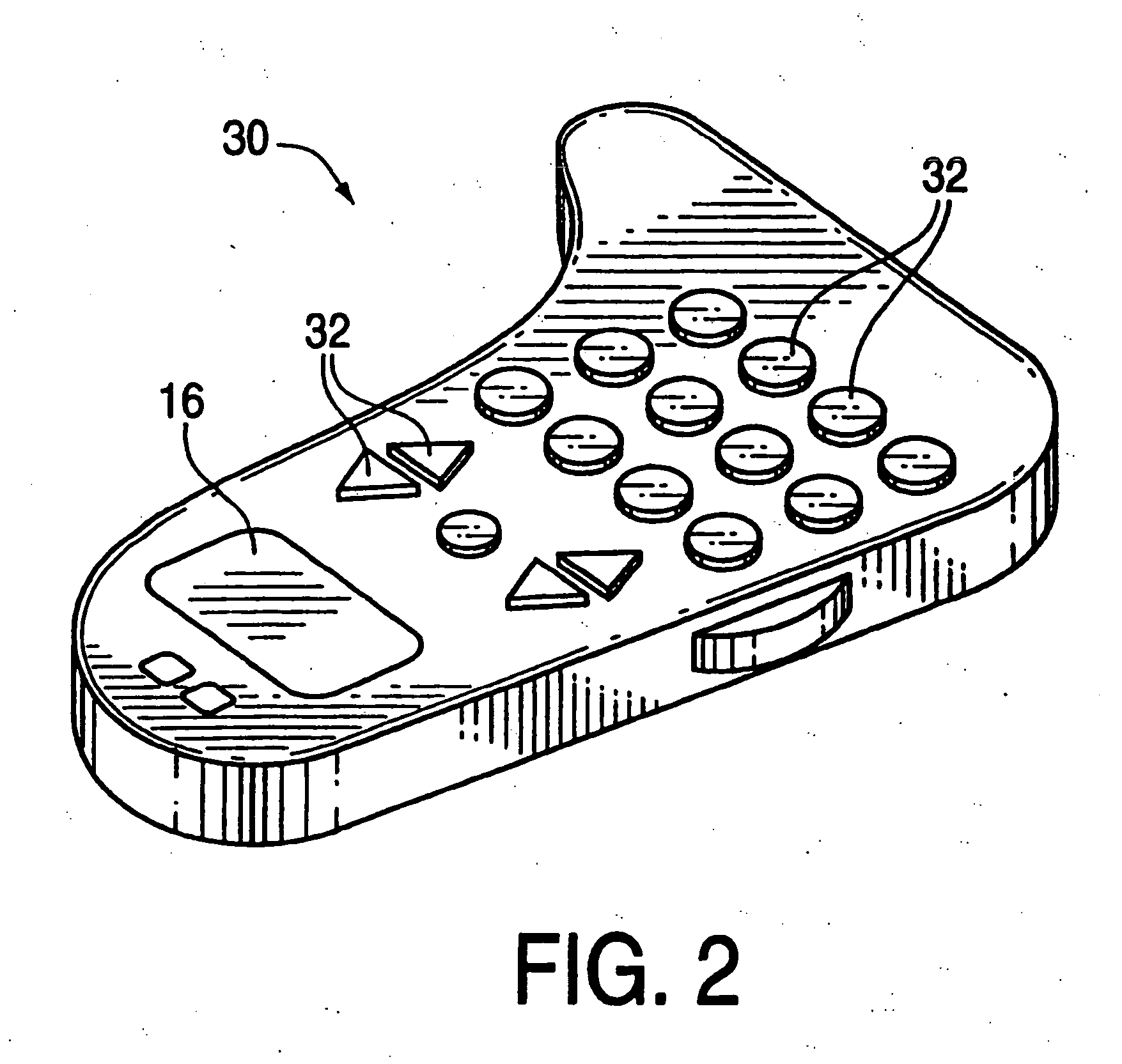
[0045] Embodiments of the present invention are described herein in the context of a system of touch input devices with haptic feedback. Sometimes these are referred to herein as touch control devices. Those of ordinary skill in the art will realize that the following detailed description of the present invention is illustrative only and is not intended to be in any way limiting. Other embodiments of the present invention will readily suggest themselves to such skilled persons having the benefit of this disclosure. Reference will now be made in detail to implementations of the present invention as illustrated in the accompanying drawings. The same reference indicators will be used throughout the drawings and the following detailed description to refer to the same or like parts.

[0046] In the interest of clarity, not all of the routine features of the implementations described herein are shown and described. It will, of course, be appreciated that in the development of any such actua...


PUM


Abstract

A planar touch control is used to provide input to a computer and haptic feedback is provided thereto. A touch control includes a touch input device with a planar touch surface that inputs a position signal to a processor associated with the computer based on a location of user implemented contact on the touch surface. The computer can position or modify a cursor or image in a displayed graphical environment based at least in part on the position signal, or perform a different function. At least one actuator is also coupled to the touch input device and outputs a force to provide a haptic sensation to the user via the touch surface.

Description

CROSS REFERENCE TO RELATED APPLICATIONS [0001] This application claims the benefit of U.S. Provisional Patent Application Ser. No. 60 / 616,648 filed Oct. 8, 2004 in the name of the same inventors and commonly assigned herewith. [0002] This application may be considered to be related to the following prior patents and patent applications: U.S. patent application Ser. No. 10 / 615,986, filed Jul. 10, 2003, which is, in turn, a continuation of U.S. patent application Ser. No. 10 / 213,940, filed Aug. 6, 2002, which is, in turn, a continuation of U.S. patent application Ser. No. 09 / 487,737, filed Jan. 19, 2000, now U.S. Pat. No. 6,429,846, which is, in turn, a continuation-in-part of U.S. patent application Ser. No. 09 / 467,309, filed Dec. 17, 1999, now U.S. Pat. No. 6,563,487, which is, in turn, a continuation-in-part of U.S. patent application Ser. No. 09 / 156,802, filed Sep. 17, 1998, now U.S. Pat. No. 6,184,868, which is, in turn, a continuation-in-part of U.S. patent application Ser. No. ...

Claims


Application Information

Patent Timeline
IPC IPC(8): G09G5/00G06F3/041
CPCG06F3/016G06F3/03547G06F3/041G06F3/0485G06F3/04886G06F2203/013G06F2203/014
Inventor GRANT, DANNY A.GREGORIO, PEDROHEUBEL, ROBERT W.RAMSTEIN, CHRISTOPHE
Owner IMMERSION CORPORATION
Why Eureka
Try Eureka