
Combustion body which produces a multi-colored flame

Inactive Publication Date: 2006-05-25
WILSON RAYMOND
View PDF37 Cites 1 Cited by
  • Summary
  • Abstract
  • Description
  • Claims
  • Application Information

AI Technical Summary

Benefits of technology

[0005] The present invention has a combustion control ring that has a claw-like restraining device that expands internally in the top part of the combustion body. The flame in the combustion body is prevented from spreading sideways.
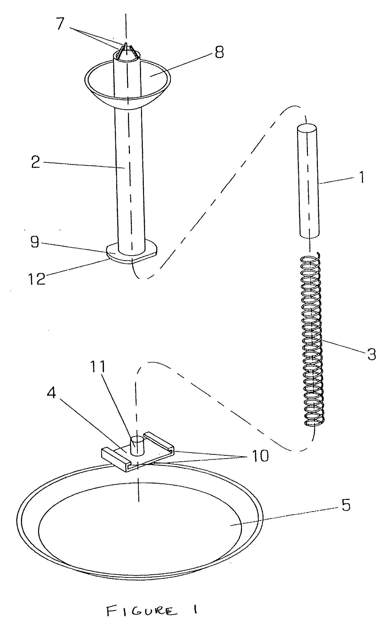
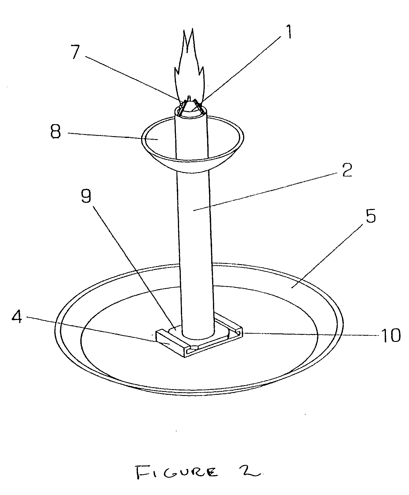
[0008] The cylinder shape combustion body can be burnt to the last minute with the tube in hand, and if the tube is fixed in a stand, the coloring flame will keep burning in a constant position. Burning ash is prevented from dispersing by installing an ash receiver on the upper side part of the tube. Heat in the upper part of the tube can also be dissipated by the ash receiver. To burn the combustion body by the method above-mentioned, it is necessary to insert the combustion body in the tube with the top part of the combustion body stopped with the claw-like restraining device in the upper part of the tube and the bottom of the combustion body pushed with a spring. Therefore, it should have the structure that either the claw-like restraining device or the spring of the tube can be detached. The former is a structure to compose the tube of a main body and detachable cap, and to install claw-like restraining device in the cap. Alternatively, the base can be made detachable.
[0009] The structure at the present invention makes burning possible when holding the apparatus or at a high position on a table by lengthening the tube, and installing the spring base in the middle part. Moreover, when the tube is not long, the spring base can be installed in the bottom of the tube. When the tube is installed on a stand, the upper surface of the stand can be used as the spring base. In this case, the tube is prevented from coming off the stand to the surface by a slot and projection in the tube.

Problems solved by technology

Even if the combustion body shortens, the combustion body is always pushed upward on the device by the spring installed in the bottom, and can burn with the claw-like restraining device in the top of the device while always staying in the top of the tube.

Method used


Image

  • Combustion body which produces a multi-colored flame
  • Combustion body which produces a multi-colored flame
  • Combustion body which produces a multi-colored flame

Examples


second embodiment

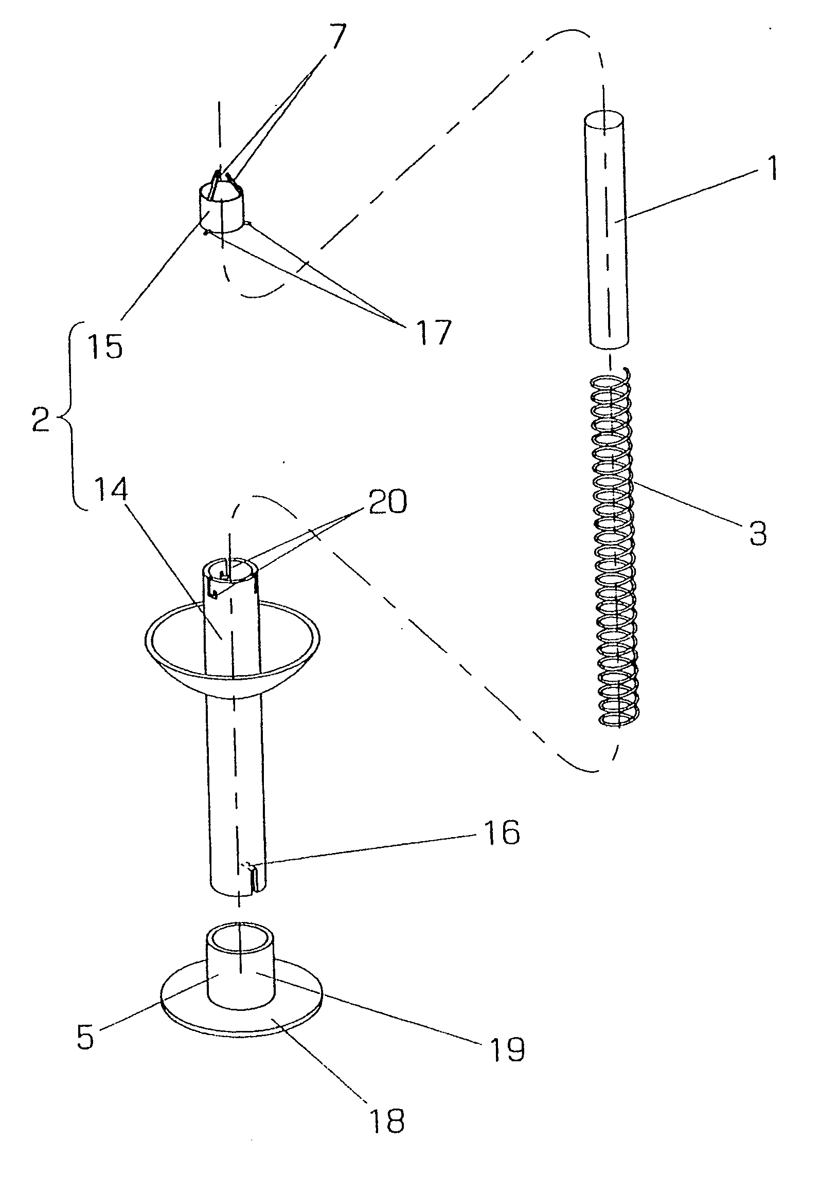
[0020] In the above-mentioned example of the second embodiment, the cap 15 is removed and the spring 5 and the combustion body 1 are inserted in the tube 14, and the combustion body 1 is pushed down into the tube 14 by the cap 15. The cap 15 is connected with the main body by inserting the projections 17 of the cap 15 in L-shaped slots 20 and then rotated. Because the cap 15 is pushed up by the expansion power of the spring 3, the projections 17 will be fixed in slots 20. Thus, the cap 5 will not be pushed off. The tube 14 can be held by hand or placed on the stand 5. The tip of the combustion body 1 located just above the rim of the tube 14 can be ignited. In the alternative embodiment, the stand 5 has a support pipe 19 and flat disc 18 welded together. The tube 14 can be placed inside pipe 19 for support.

third embodiment

[0021]FIG. 5 shows a third embodiment in which the main body of tube 2 is lengthened, and the spring base 5 can be fixed in the middle of the tube 2. In this example, splinters 16 are bent internally as also shown in FIG. 4, but the splinters 16 are placed in the middle of tube 2. The reference numeral 21 represents a point on tube 2 at which splinters 16 can be placed.


PUM


Abstract

A cylindrically shaped combustion body of several metals or compounds like alkaline, metal or copper, which when burned produce multi-colored flames without a wick or liquid contents, and holds the flame in a stable position. As the cylindrically shape combustion body burns up, a spring mechanism pushes it upward through a tube, and a claw-like restraining device at the top of the tube keeps the combustion body from emerging out of the tube. Thus, the tip of the combustion body is held just above the rim of the tube, and the flame remains in a constant position, even as the combustion body burns shorter.

Description

BACKGROUND OF THE INVENTION [0001] 1. Field of the Invention [0002] This invention relates to a wickless cylindrically shaped combustion body which contains alkaline metal, alkaline earth metal, and copper, which when burned produce multi-colored flames. [0003] 2. Discussion of the Prior Art [0004] It is known in the prior art to present a combustion body or candle having a metallic compound mixed with wax such that when the candle burns a vivid colored light is emitted. Typically, lithium or copper can be used with the wax to produce this effect. These candles can be placed on a table or the like. A problem arose, however, in that the candle burned too fast. The entire top face of the candle would burn and in a short time the desirable effect from its unusual light was finished. This problem is common to wickless combustion bodies or candles. The present invention teaches a means to burn a cylindrically shaped wickless combustion body including the metallic compound, which presents...

Claims


Application Information

Patent Timeline
IPC IPC(8): F23D3/16
CPCF23D3/16F23D3/24F23D3/40
Inventor NISHI, TAKEO
Owner WILSON RAYMOND
Learn More