Dynamic stabilization assemblies, tool set and method

a technology of dynamic stabilization and tool set, applied in the field of spinal surgery apparatus and methods, can solve the problems of catching and traumatizing tissues, oversized or irregular surfaces or protrusions, and affecting the patient's recovery, so as to achieve easy attachment to and disengagement from bone attachment implants, and minimal or less surgical invasion of patients.

Active Publication Date: 2006-05-25
NUVASIVE
View PDF99 Cites 608 Cited by
  • Summary
  • Abstract
  • Description
  • Claims
  • Application Information

AI Technical Summary

Problems solved by technology

Problems arise when implant deployment and insertion tools designed for traditional open surgery that is more invasive are utilized in percutaneous or less invasive surgery or with dynamic stabilization longitudinal connecting members.
The tools may be bulky, oversized or have irregular surfaces or protrusions that can catch and traumatize tissues.
A projecting actuator arm or fastening member may be useful with respect to the spinal screw implantation process or the rod reduction process, but there may be insufficient clearance to use such structure and / or such structure may produce additional unwanted trauma which the percutaneous surgery is attempting to avoid.
A percutaneous or less invasive procedure also presents a problem with implantation of elongate connecting members that have historically required a long incision and open wound in order to provide for the length of the connecting member and the space required for the surgeon's hands as well as the tools needed to manipulate the rod.
Such problems are then compounded by the implants and insertion tools used with the connecting member.
Fusion, however, has some undesirable side effects.
Furthermore, although fusion may result in a strengthened portion of the spine, it also has been linked to more rapid degeneration and even hyper-mobility and collapse of spinal motion segments that are adjacent to the portion of the spine being fused, reducing or eliminating the ability of such spinal joints to move in a more normal relation to one another.
In certain instances, fusion has also failed to provide pain relief.
Tools utilized with traditional rods or other more rigid structure may not be appropriate for manipulating more flexible connecting members and cooperating bone attachment structures.
The dynamic conditions associated with spinal movement therefore provide a challenge not only for the design of elongate elastic longitudinal connecting members, but also for the design of cooperating bone attachment structure and tooling.

Method used


Image

  • Dynamic stabilization assemblies, tool set and method
  • Dynamic stabilization assemblies, tool set and method
  • Dynamic stabilization assemblies, tool set and method

Examples


Embodiment Construction

[0079] As required, detailed embodiments of the present invention are disclosed herein; however, it is to be understood that the disclosed embodiments are merely exemplary of the invention, which may be embodied in various forms. Therefore, specific structural and functional details disclosed herein are not to be interpreted as limiting, but merely as a basis for the claims and as a representative basis for teaching one skilled in the art to variously employ the present invention in virtually any appropriately detailed structure.

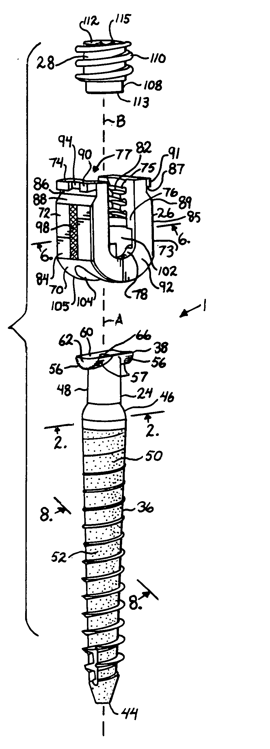
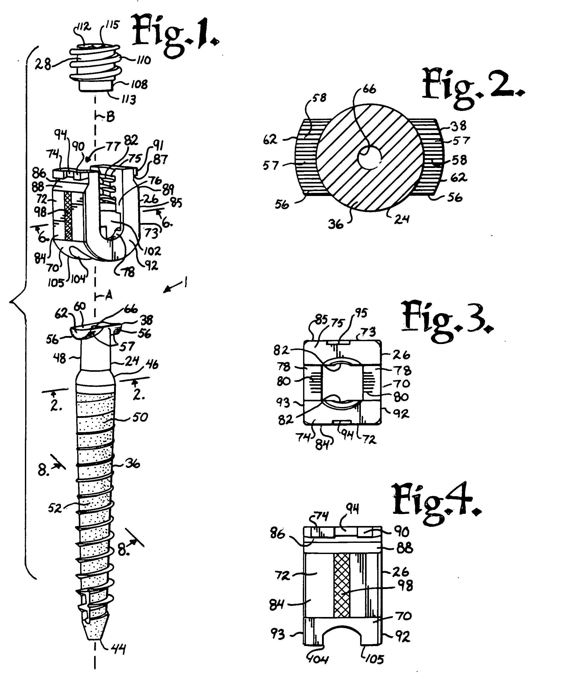
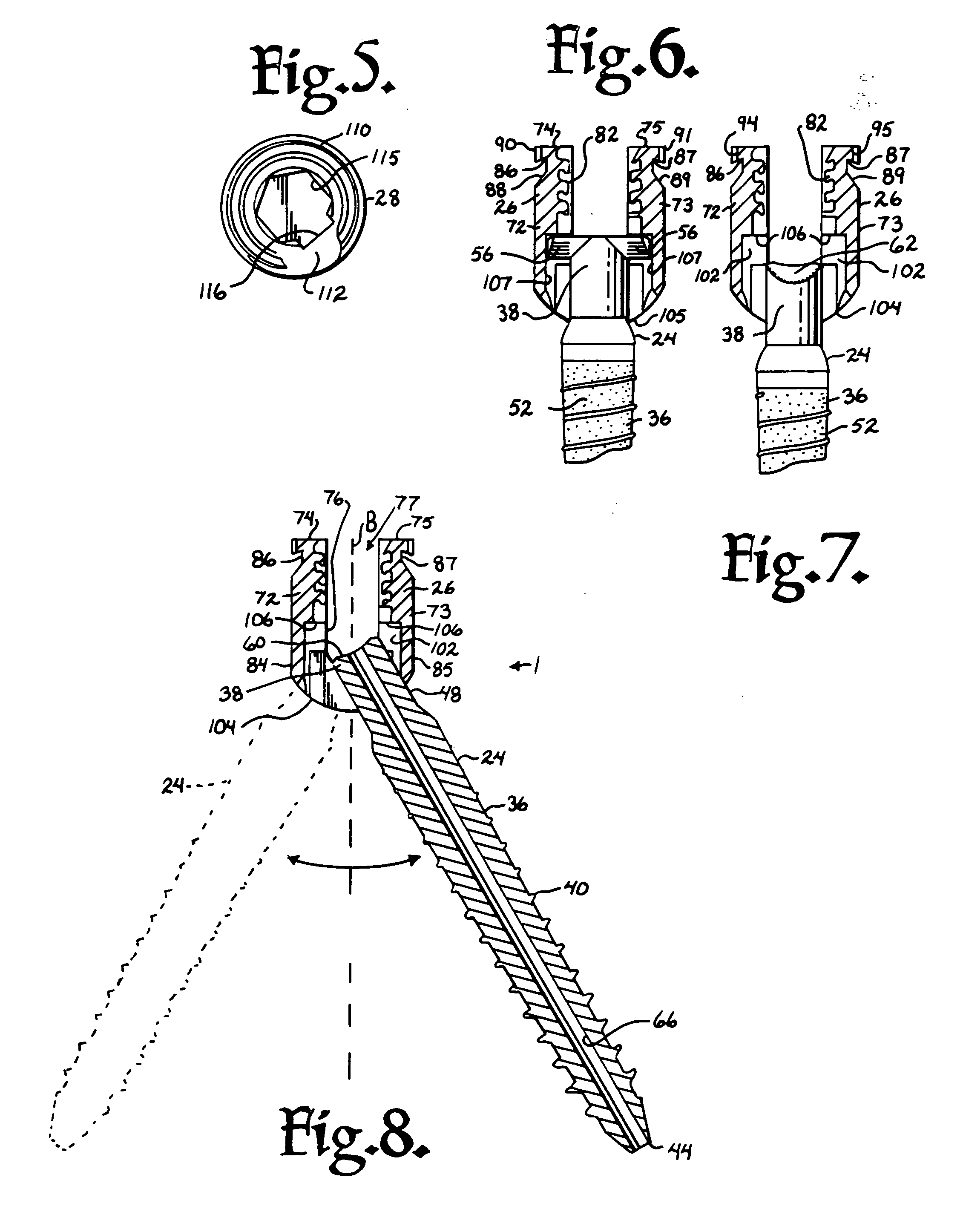
[0080] With reference to FIGS. 1-38, the reference numeral 1 generally designates a hinged bone screw for cooperation with a dynamic stabilization connecting member, generally 3, such as the illustrated cord 6 with cannulated spacers 8. The spacers 8 are substantially cylindrical with opposed planar sides 9. Tools for implanting a bone screw 1 on a vertebra 10 of a human spine 12 and manipulating cooperating bone screws 1 and longitudinal connecting members...


PUM


Abstract

A hinged bone screw and tool set is used for implanting such bone screws in a human spine, followed by the implantation of a longitudinal connecting member into the bone screws. The hinged bone screw includes a shank with an upper portion and a receiver with integral arms forming a U-shaped channel. A lower curved seat partially defining the U-shaped channel cooperates with an upper portion of the bone screw shank for hinged movement of the shank with respect to the receiver. The tool set includes an insertion tool, a bone screw driver, a reduction tool and a closure starter. The insertion tool includes a bone screw attachment structure and a laterally opening channel. The insertion tool further includes a threaded portion for cooperation with the reduction tool to provide synchronized placement of a closure structure in the bone screw receiver while reducing and capturing a longitudinal connecting member within the receiver. Further alternative bone screws are hinged, polyaxial or fixed and include lordosing or kyphosing lateral surfaces.

Description

CROSS-REFERENCE TO RELATED APPLICATIONS [0001] This application is a continuation-in-part of U.S. patent application Ser. No. 11 / 272,508 filed Nov. 10, 2005 that claims the benefit of U.S. Provisional Application No. 60 / 630,536 filed Nov. 23, 2004; and is a continuation-in-part of U.S. patent application Ser. No. 10 / 996,289 filed Nov. 23, 2004; and also is a continuation-in-part of U.S. patent application Ser. No. 10 / 789,149, filed Feb. 27, 2004, all of which are incorporated herein by reference. This application also claims the benefit of U.S. Provisional Application No. 60 / 722,300 filed Sep. 30, 2005; U.S. Provisional Application No. 60 / 725,445 filed Oct. 11, 2005; U.S. Provisional Application No. 60 / 728,912 filed Oct. 21, 2005 and U.S. Provisional Application No. 60 / 736,112 filed Nov. 10, 2005, all of which are incorporated herein by reference.BACKGROUND OF THE INVENTION [0002] The present invention relates to apparatuses and methods for use in performing spinal surgery and, in p...

Claims


Application Information

Patent Timeline
Patent Type & Authority Applications(United States)
IPC IPC(8): A61F2/30
CPCA61B17/7004A61B17/861A61B17/7028A61B17/7031A61B17/7032A61B17/7037A61B17/7038A61B17/7076A61B17/7082A61B17/7085A61B17/7089A61B17/7091A61B17/8875A61B17/7002A61B17/7011
Inventor JACKSON, ROGER P.
Owner NUVASIVE
Why Eureka
Try Eureka