Al technical title is built by PatSnap Al team. It summarizes the technical point description of the patent document.
a battery charger and power tool technology, applied in the field of power tools, battery chargers and batteries, can solve the problems of limited play or rattle between the battery and the electrical component, and achieve the effect of reducing fretting corrosion and excessive wear
Inactive Publication Date: 2006-06-01
MILWAUKEE ELECTRIC TOOL CORP
View PDF38 Cites 8 Cited by
Summary
Abstract
Description
Claims
Application Information
AI Technical Summary
This helps you quickly interpret patents by identifying the three key elements:
Problems solved by technology
Method used
Benefits of technology
[0004] In some aspects and in some constructions, an electrical component, such as a power tool or battery charger, generally includes a housing, a battery connector or support supported by the housing and a member positionable between a portion of a power tool battery and one of the housing and the battery support to limit movement of the battery relative to the one of the housing and the support. In such aspects and in such constructions, any play or rattle between the battery and the electrical component is limited. Also, movement between the male and female terminals during use is reduced to eliminate fretting corrosion and excessive wear.
Problems solved by technology
In such aspects and in such constructions, any play or rattle between the battery and the electrical component is limited.
Method used
Image
Click on the blue label to locate the original text in one second.
Reading with bidirectional positioning of images and text.
Examples
Embodiment Construction
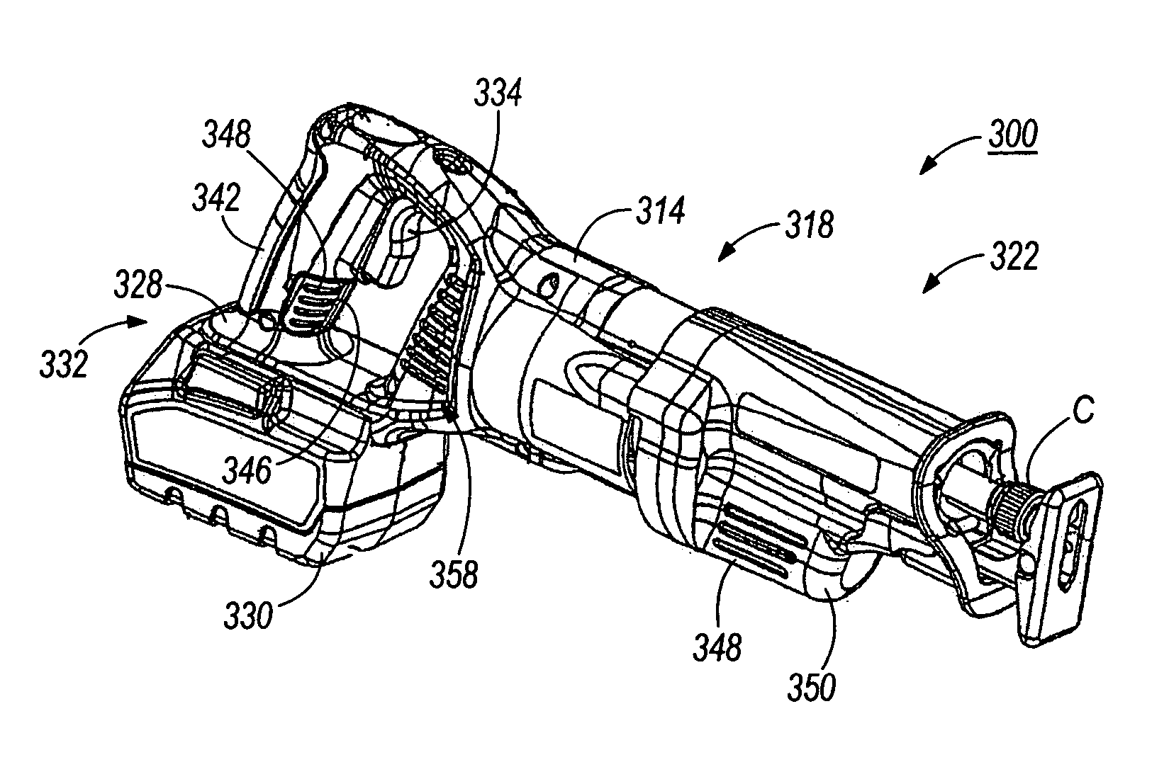
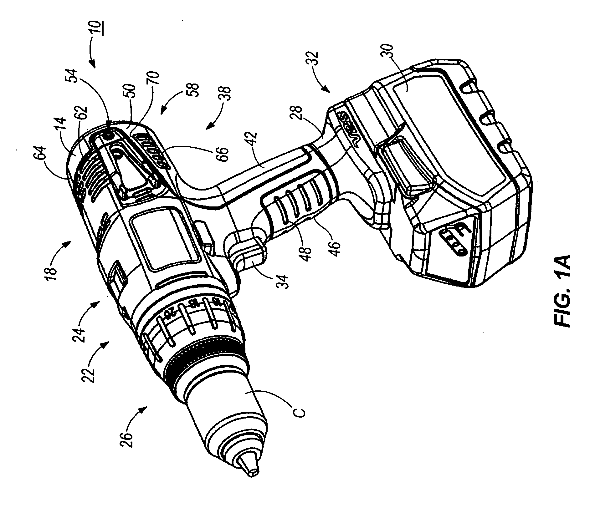
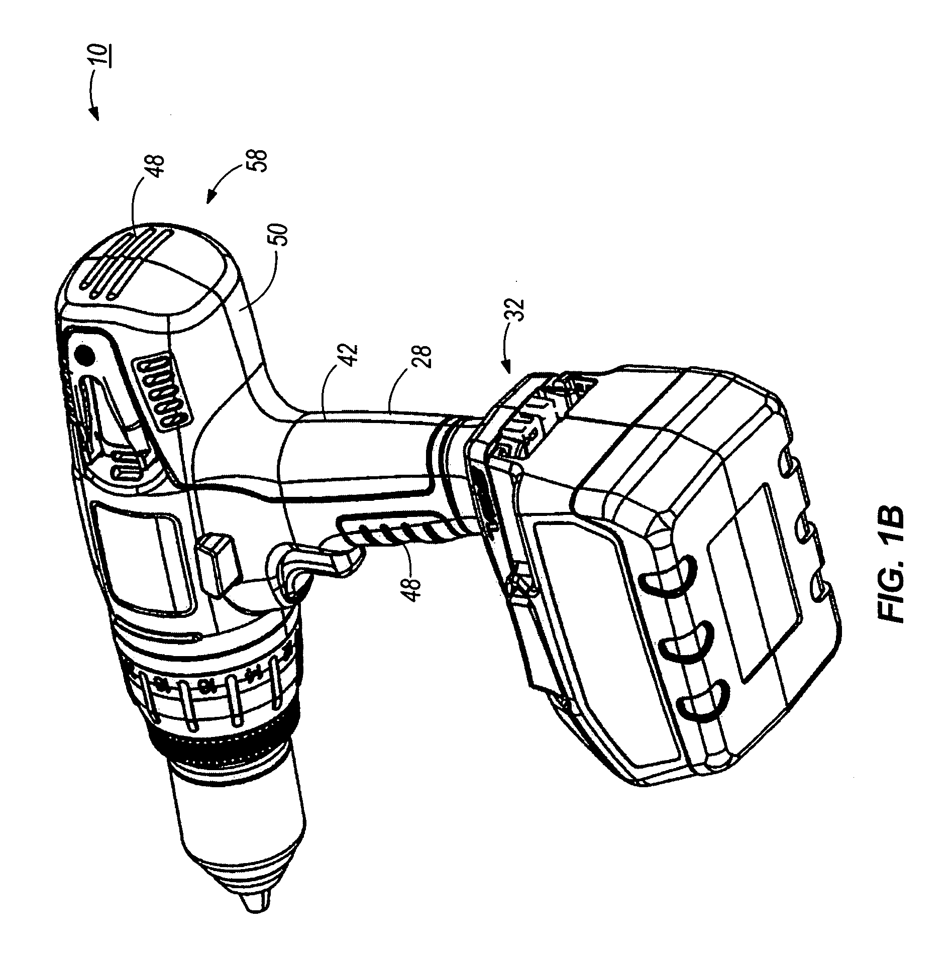
[0043]FIGS. 1A-1H illustrate a power tool, such as, for example a hammer-drill 10, a drill or a screwdriver, embodying one or independent aspects of the invention. The hammer-drill 10 includes a housing body 14 supporting a motor 18 which is operable to drive a transmission 22. A chuck C is supported on a spindle (not shown) and is driven by the motor 18 and the transmission 22 for rotation and, in the illustrated construction, for selective reciprocation. The chuck C is operable to support a tool element, such as, for example, a drill bit.
[0044] In the illustrated construction, the transmission 22 includes a 2-speed planetary gear arrangement (not shown). An actuator 24 is supported on the housing 14 and is operable to adjust the condition of the transmission 22 between a first speed and torque setting and a second speed and torque setting. In the illustrated construction, the actuator 24 is movable laterally relative to the axis of the housing 14 to cause axial movement of the ri...
PUM
Property
Measurement
Unit
voltage
aaaaa
aaaaa
angle
aaaaa
aaaaa
angle
aaaaa
aaaaa
Abstract
A power tool including a body housing a motor and a drive mechanism driven by the motor, the drive mechanism being operable to drive a tool element, the body including a support portion, a battery electrically connectable with the motor such that the battery selectively supplies power to the motor, the battery including an adapter support portion connectable to the body support portion along an adapter attachment axis, one of the support portion of the body and the adapter support portion of the battery including a track and a ramp positioned along the track and angled with respect to the attachment axis, and an other of the support portion of the body and the adapter support portion of the battery including a protrusion engageable with the track to connect the battery to the body and engageable with the ramp.
Description
RELATED APPLICATIONS [0001] The present patent application claims the benefits of prior filed co-pending U.S. provisional patent application Ser. No. 60 / 625,151, filed on Nov. 4, 2004, the entire contents of which are herby incorporated by reference.FIELD OF THE INVENTION [0002] The present invention relates to power tools, battery chargers and batteries. SUMMARY OF THE INVENTION [0003] In some aspects and in some constructions, an electrical component, such as a power tool or a battery charger, generally includes a housing and a modular battery interface or connector supported by the housing. [0004] In some aspects and in some constructions, an electrical component, such as a power tool or battery charger, generally includes a housing, a battery connector or support supported by the housing and a member positionable between a portion of a power tool battery and one of the housing and the battery support to limit movement of the battery relative to the one of the housing and the sup...
Claims
Application Information
Patent Timeline
Application Date:The date an application was filed.
Publication Date:The date a patent or application was officially published.
First Publication Date:The earliest publication date of a patent with the same application number.
Issue Date:Publication date of the patent grant document.
PCT Entry Date:The Entry date of PCT National Phase.
Estimated Expiry Date:The statutory expiry date of a patent right according to the Patent Law, and it is the longest term of protection that the patent right can achieve without the termination of the patent right due to other reasons(Term extension factor has been taken into account ).
Invalid Date:Actual expiry date is based on effective date or publication date of legal transaction data of invalid patent.
Patent Type & Authority Applications(United States)
Inventor SERDYNSKI, DAVID P.MILLER, BOYD J.BUBLITZ, SCOTT D.THORSON, TROY C.BEDNAR, THOMAS R.GRIEP, DAVID B.UEHLEIN-PROCTOR, NANCYGRZYBOWSKI, DENNIS J.HOLLY, JEFFREY S.HESSENBERGER, JEFFREY C.KUBALE, MARK A.JOHNSON, TODD W.LOBERT, JONATHAN P.ROSENBECKER, JAY J.