Multifunctional submersible mixed transportation vortex pump

A multi-functional, swirl pump technology, applied in radial flow pumps, special fluid pumps, pumps, etc., can solve the problems of high temperature resistance, pipeline damage, uneconomical, etc., and achieve strong abrasion resistance and high processing viscosity , the effect of improving efficiency

Inactive Publication Date: 2015-02-04
DONGYING CITY XIN BAO MACHINERY MFG
View PDF9 Cites 1 Cited by
  • Summary
  • Abstract
  • Description
  • Claims
  • Application Information

AI Technical Summary

Problems solved by technology

[0002] There is an existing screw pump, whose structure is a combination of an eccentric screw and a rubber stator, which contributes to the mixed transportation and oil recovery of petroleum, but it also has the following shortcomings or deficiencies: ①The pump body passes through pressure and transports mechanical components (such as gears, The plunger, diaphragm, rotor, blade, etc.) are in contact with each other to convey the material medium, and the mechanical parts have a serious impact on the pump body and the material, and the life reliability is poor; ② For conveying high-viscosity medium, abrasive medium, medium containing solid particles, The medium of gas foam and the medium sensitive to shear force will produce pulsation, which will cause great wear and tear on the pump, damage the pipeline, and limit the depth of the pump; ③ it is not suitable for harsh working conditions. High viscosity, abrasiveness, strong corrosion and other occasions, the performance of the pump is seriously reduced; ④Narrow displacement range, not resistant to high temperature, low efficiency, more maintenance, short service life, uneconomical

Method used


Image

  • Multifunctional submersible mixed transportation vortex pump
  • Multifunctional submersible mixed transportation vortex pump
  • Multifunctional submersible mixed transportation vortex pump

Examples


Embodiment Construction

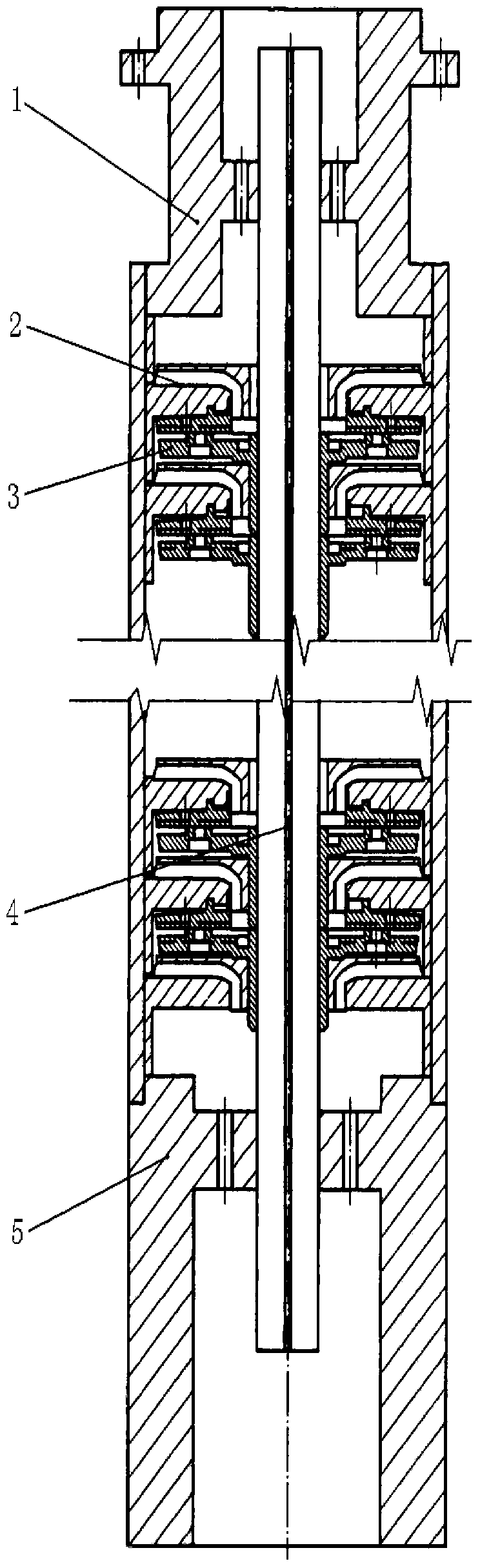
[0019] refer to Figure 1-Figure 3 , a multi-functional submersible mixed transport swirl pump, including a suction port 1, guide impeller 2, swirl impeller 3, pump shaft 4 and discharge head 5. The suction port 1 is connected and installed in sequence with the vane wheel 2, the swirl impeller 3 and the discharge head 5, and the pump shaft 4 runs through the center of the suction port 1, the vane wheel 2, the swirl wheel 3 and the discharge head 5.

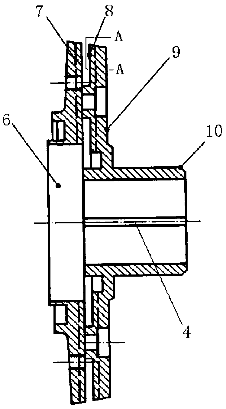
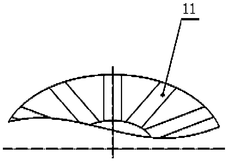
[0020] The swirl impeller 3 comprises an upper cover plate 9 and a lower cover plate 7 installed together, the upper cover plate 9 is equipped with an upper cover plate petiole 10, the lower cover plate 7 is provided with an impeller suction port 6, the upper cover plate 9 and The lower cover plate 7 is respectively provided with 3-16 raised corrugated strips 11, which are shown as 12 in the figure. Between the upper cover plate 9 and the lower cover plate 7 is provided a fluted runner discharge port 8 . There is a gap between t...


PUM


Abstract

The invention discloses a multifunctional submersible mixed transportation vortex pump. The vortex pump comprises a suction inlet, a guide impeller, a vortex impeller, a pump shaft and a discharge head, wherein the suction inlet is connected with the guide impeller, the vortex impeller and the discharge head in sequence into a whole; the pump shaft penetrates through the centers of the suction inlet, the guide impeller, the vortex impeller and the discharge head. The vortex pump has the characteristics of high corrosion resistance, freeness from collision components, low required power, high treatment viscosity, high efficiency, prevention of emulsification effect on well fluid, multiple functions, high suitability, realization of mixed transportation of gas and liquid, fundamental elimination of blockage, cavitation, excessive wear, running reliability, high efficiency, low maintenance, long service life and the like, and is widely applied to petroleum suction and conveying processes; the treatment viscosity of viscous media is up to 300,000Pa.c, the required power is low and is not up to a half that of a pump of the same specification, blockage is prevented, the conveying percent of solid particles is up to 75 percent, high and low-viscosity well fluid of which the gas content is up to 68 percent can be conveyed, and all the phenomena influencing the pump performance such as blockage, cavitation, excessive wear, damage and the like are avoided fundamentally.

Description

technical field [0001] The invention relates to a submersible oil transfer pump, in particular to a multifunctional submersible oil mixed transfer swirl pump. Background technique [0002] There is an existing screw pump whose structure is a combination of an eccentric screw and a rubber stator, which contributes to the mixed oil production of oil, but it also has the following shortcomings or deficiencies: ①The pump body passes through pressure and transports mechanical components (such as gears, gears, etc.) Plunger, diaphragm, rotor, vane, etc.) are in contact with each other to convey the material medium, and the mechanical parts have a serious impact on the pump body and the material, and the life reliability is poor; ② For conveying high-viscosity medium, abrasive medium, medium containing solid particles, containing The medium of gas foam and the medium sensitive to shear force will produce pulsation, which will cause great wear and tear on the pump, damage the pipeli...

Claims


Application Information

Patent Timeline
Patent Type & Authority Applications(China)
IPC IPC(8): F04D1/06F04D7/04F04D29/22
CPCF04D1/06F04D7/045F04D29/2211F04D29/2216F04D29/2288
Inventor 王英敏
Owner DONGYING CITY XIN BAO MACHINERY MFG
Why Eureka
Try Eureka