Buffer element and power head buffer device with same

A technology of buffer element and impact head, applied in the direction of spring, shock absorber, spring/shock absorber, etc., can solve the problems of the guide rod cannot be ejected, the buffer effect is poor, and the dynamic sealing performance is poor, so as to reduce the processing difficulty and processing. Cost, Guaranteed Cushioning and Shock Absorption, Guaranteed Cushioning and Shock Absorption

Pending Publication Date: 2021-06-04
西安托普森工业自动化有限公司
View PDF11 Cites 1 Cited by
  • Summary
  • Abstract
  • Description
  • Claims
  • Application Information

AI Technical Summary

Problems solved by technology

[0006] ①. There is no cement buffer element applied to the rotary drilling rig in the prior art;
[0007] ②. For the cement buffer element in the prior art, there is no dust-proof design on the upper end of the guide sleeve, which is easy to enter impurities such as sediment, which will cause problems such as sticking, transitional wear and even shaking of the cylinder;
[0008] ③. Oil pressure buffer components are prone to oil leakage: when subjected to high-frequency and small vibrations, the dynamic sealing performance of high-pressure oil is poor, and oil leakage is prone to occur; there is more muddy water in the working environment of rotary drilling rigs, which is likely to cause seal failure. Oil leakage due to early failure; when the oil pressure buffer element is subjected to overload impact, it is easy to damage the seal, resulting in oil leakage;
[0009] ④. Due to oil leakage and other similar problems of the oil pressure buffer element, the pressure drops, and eventually the guide rod cannot be ejected and the buffer fails;
[0010] ⑤. The sealing requirements of the oil pressure buffer element are high, which makes its manufacturing precision higher, which leads to an increase in cost
[0011] In view of this, the present invention provides a buffering element and a power head buffering device using cement for buffering, so as to solve the problems of insufficient shock-absorbing capacity and poor buffering effect of the buffering element on the rotary drilling rig, especially the rubber buffering element, and at the same time avoid Solved the problems of oil leakage in the oil pressure buffer element and the non-rebound of the guide rod, etc.

Method used


Image

  • Buffer element and power head buffer device with same
  • Buffer element and power head buffer device with same
  • Buffer element and power head buffer device with same

Examples


Embodiment 1

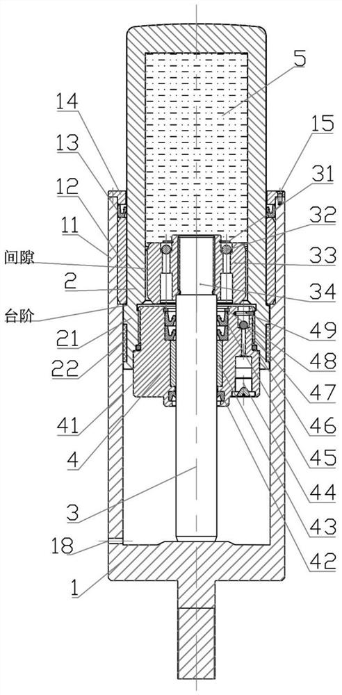
[0057] refer to figure 1 As shown, a buffer element includes an outer cylinder assembly 1, an inner cylinder assembly 2 and a piston rod assembly 3. The improvement is that the outer cylinder assembly 1 includes an inner The outer cylinder body 11 of the cylinder body assembly 2 and the piston rod assembly 3, the outer cylinder body 11 is in sliding and sealing connection with the inner cylinder body 21 of the inner cylinder body assembly 2, and the end of the inner cylinder body 21 is connected to the end cover of the inner cylinder body Assemblies 4, the inner cylinder end cover assembly 4 is in sliding sealing connection with the piston rod 34 of the piston rod assembly 3, the piston rod 34 is connected with the impact head 33, the gap between the impact head 33 and the inner cylinder body 21 Cooperate, the inner cavity of the inner cylinder 21 is injected with elastic cement 5; the end of the inner cylinder 21 exposed to the outer cylinder 11 slides downward in the outer c...

Embodiment 2

[0063] On the basis of embodiment 1, with reference to figure 1 As shown, the outer cylinder assembly 1 also includes a copper sleeve I12, a skeleton oil seal I13 and an outer cylinder end cover 14. Sliding fit, the skeleton oil seal I13 is arranged on the upper end of the copper sleeve I12, and the outer cylinder body end cover 14 is arranged at the port of the outer cylinder body 11 and is clearance-fitted with the inner cylinder body 21.

[0064] Further, the end cover 14 of the outer cylinder body is fixed on the port of the outer cylinder body 11 by screws 15 .

[0065] Further, the copper sleeve I12 is a self-lubricating copper sleeve, and the surface of the inner hole is embedded with graphite material.

[0066] In this embodiment: the copper sleeve I12 ensures that the inner cylinder body 21 moves along the axial direction in the outer cylinder body 11; the skeleton oil seal I13 seals the inner cylinder body 21, thereby preventing foreign silt and other impurities fro...

Embodiment 3

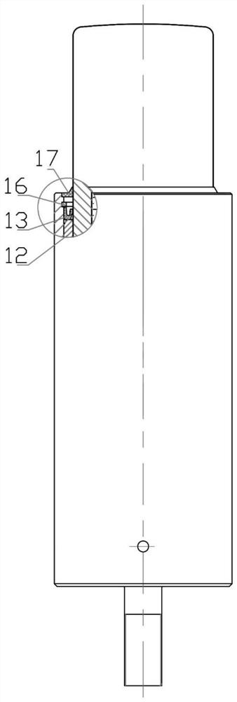
[0068] On the basis of embodiment 1, with reference to figure 2 As shown, the outer cylinder body assembly 1 also includes a copper sleeve I12, a skeleton oil seal I13, a retaining ring I16 for holes and a dust-proof strip 17, and the copper sleeve I12 is arranged on the steps of the inner wall of the outer cylinder body 11 and is connected with the The inner cylinder body 21 is slidably fitted, the skeleton oil seal I13 is arranged on the upper end of the copper sleeve I12, the hole retaining ring I16 is arranged on the upper end of the skeleton oil seal I13, and the dust-proof strip 17 is bonded to the port of the outer cylinder body 11.

[0069] Further, a groove is provided at the port of the outer cylinder body 11, and the dust-proof strip 17 is bonded in the groove.

[0070] Further, the copper sleeve I12 is a self-lubricating copper sleeve, and the surface of the inner hole is embedded with graphite material.

[0071] In this embodiment: the copper sleeve I12 ensures ...


PUM


Abstract

The invention relates to a buffer element and a power head buffer device with same., The buffer element comprises an outer cylinder body assembly, an inner cylinder body assembly and a piston rod assembly, wherein the outer cylinder body assembly comprises an outer cylinder body used for being connected to an external device and bearing the inner cylinder body assembly and the piston rod assembly; the outer cylinder body is connected to an inner cylinder body of the inner cylinder body assembly in a sliding and sealing mode, the end part of the inner cylinder body is connected to an inner cylinder body end cover assembly, the inner cylinder body end cover assembly is connected to a piston rod of the piston rod assembly in a sliding and sealing mode, the piston rod is connected to an impact head, and the impact head is in clearance fit to the inner cylinder body; an inner cavity of the inner cylinder body is filled with elastic glue; the end part, exposed out of the outer cylinder body, of the inner cylinder body slides downwards in the outer cylinder body after being impacted by load, and meanwhile, the inner cylinder body end cover assembly is driven to slide downwards along the piston rod. The buffer element has excellent buffering and shock-absorbing effects, is more reliable in usability and is longer in service life.

Description

technical field [0001] The invention relates to the field of power buffering, in particular to a buffering element and a power head buffering device with the element. Background technique [0002] The working mode of the rotary drilling rig is often the rock-entry mode, and the power head is used as the power / torque output unit, which becomes one of the most direct shock points when the rock-entry mode is subjected to vibration. Therefore, the power head is equipped with a buffer The device is equipped with different numbers and types of springs and rubber buffer elements according to buffer requirements. However, due to limitations such as structural size, the rubber buffer element cannot fully satisfy the buffer performance and cannot absorb vibrations, so that the structural parts on the power head and the housing of the reducer often suffer from cracks and cracks due to vibrations. [0003] In order to solve the problem of insufficient cushioning capacity, in the prior ...

Claims


Application Information

Patent Timeline
Patent Type & Authority Applications(China)
IPC IPC(8): F16F9/30F16F9/32F16F9/36F16F9/43
CPCF16F9/30F16F9/3235F16F9/3242F16F9/362F16F9/369F16F9/3228F16F9/435
Inventor 刘小龙朱识儒
Owner 西安托普森工业自动化有限公司
Why Eureka
Try Eureka