System, circuit and method for tuning a resonant circuit

a resonant circuit and circuit technology, applied in discontinuous tuning with variable tuning elements, instruments, etc., can solve the problems of affecting the resonant frequency of tuned circuits, and correspondingly affecting the magnetic field generated by the inductor

Active Publication Date: 2006-06-01
ALFRED E MANN FOUND FOR SCI RES
View PDF11 Cites 30 Cited by
  • Summary
  • Abstract
  • Description
  • Claims
  • Application Information

AI Technical Summary

Benefits of technology

[0011] The source may provide a square wave output. Alternatively, the source may provide a sinusoidal output. The control circuit may comprise a switch that selects the f...

Problems solved by technology

Paramount in this quest has been the challenge of efficiently providing a reliable and stable power source to power the device or charge its internal battery.
Unfortunately, such ideal circumstances are generally not possible and the effective inductance v...

Method used


Image

  • System, circuit and method for tuning a resonant circuit
  • System, circuit and method for tuning a resonant circuit
  • System, circuit and method for tuning a resonant circuit

Examples


Embodiment Construction

[0025] This description if not to be taken in a limiting sense, but is made merely for the purpose of describing the general principles of the embodiments of the invention.

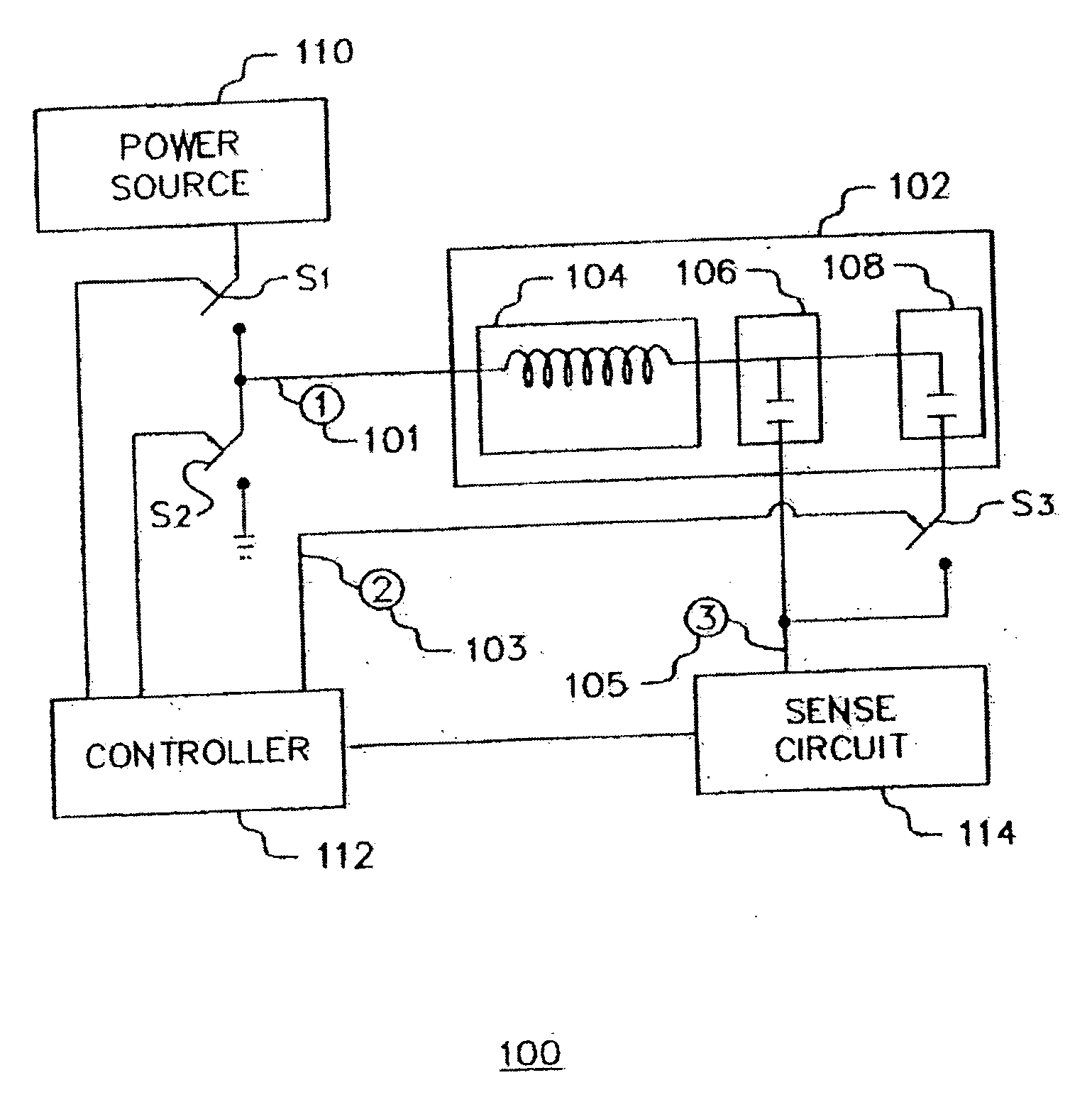
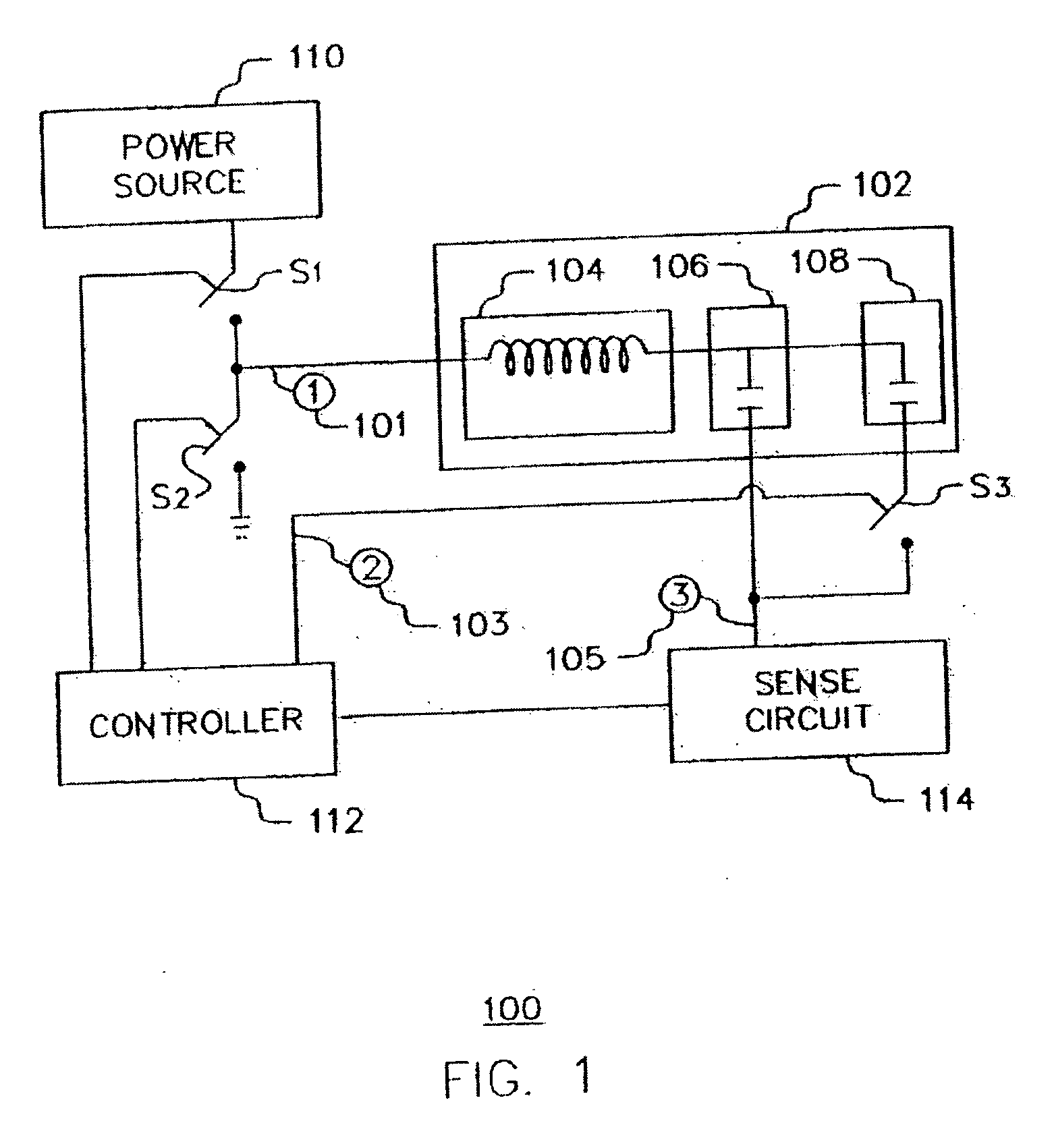
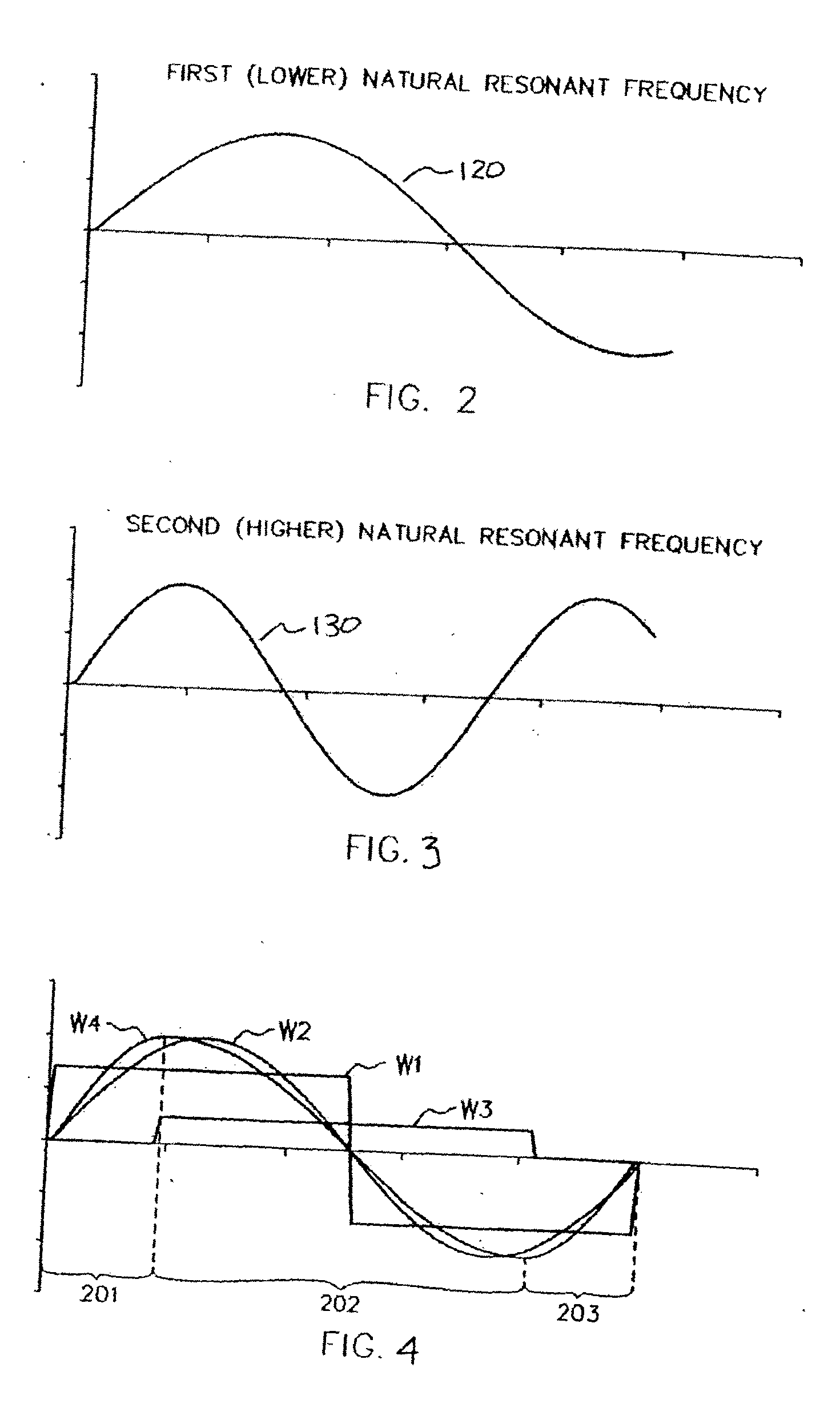
[0026]FIG. 1 is a schematic diagram of a tuning system or circuit in accordance with a first embodiment of the present invention. The tuning system 100 comprises a tunable resonant circuit 102 comprising an inductor 104, a primary capacitor 106, and a secondary capacitor 108. As will be seen subsequently, the capacitor 108 is switchable in and out of parallel circuit with capacitor 106. The inductor 104 and capacitors 106 and 108 from a series resonant circuit having a first or lower resonant frequency when capacitor 108 is switched in circuit and a second or higher resonant frequency when capacitor 108 is switched out of circuit.

[0027] The tuning system 100 further comprises a power source 110. The power source 110 provides power at a first predetermined drive frequency to the tunable resonant circuit 102. To t...


PUM


Abstract

A circuit may be tuned to resonate at a driving frequency. The circuit includes a source that provides an output at a drive frequency and a resonant circuit having an input coupled to the source, an output, and first and second selectable resonant frequencies. The first resonant frequency is below the drive frequency and the second resonant frequency is above the drive frequency. A control coupled to the resonant circuit output selects the first and second resonant frequencies to cause the resonant circuit to provide an output at an apparent resonant frequency equal to the drive frequency.

Description

CLAIM OF PRIORITY [0001] This application claims priority to U.S. Provisional Application Ser. No. 60 / 632,721, filed on Dec. 1, 2004, which is incorporated by reference.BACKGROUND OF THE INVENTION [0002] Implantable medical devices for remedial treatment of and compensation for cardiac, neural and muscular disorders are known in the art. These devices range from cardiac pacemakers as described in U.S. Pat. No. 4,712,555 to Thornander et al., to microstimulators as described in U.S. Pat. No. 6,208,894 to Schulman et al. The quest for minimization of such devices, especially in the area of microdevices such as microstimulators and microsensors continues. Paramount in this quest has been the challenge of efficiently providing a reliable and stable power source to power the device or charge its internal battery. The quest has further addressed the communication medium to facilitate information, data and command signal transfer and exchange between the microdevice and a corresponding mic...

Claims


Application Information

Patent Timeline
IPC IPC(8): G05F1/656
CPCA61N1/08A61N1/378H03J5/02
Inventor STOVER, HOWARD H.HEINER, GARY L.
Owner ALFRED E MANN FOUND FOR SCI RES
Why Eureka
Try Eureka