Audio visual system

a technology of audio visual system and video device, applied in the field of audio visual system, can solve the problem of ineffective remote control, achieve the effect of avoiding unnecessary video display, and easy operation of video device corresponding

Active Publication Date: 2008-05-27
PANASONIC CORP
View PDF16 Cites 54 Cited by
  • Summary
  • Abstract
  • Description
  • Claims
  • Application Information

AI Technical Summary

Benefits of technology

[0010]According to a third aspect of the present invention, there is provided an audio visual system comprising a display unit, a plurality of video devices connected to the display unit, and remote controllers for controlling the respective video devices, wherein one of the remote controllers transmits a remote control code to the display unit; the display unit adds a header to the remote control code transmitted from the remote controller, and transmits the remote control code to the respective video devices in unison; and each of the video devices checks as to whether the remote control code is directed to itself or not on the basis of a device address that is included in the header of the signal received from the display unit, and operates according to a remote control command that is included in the remote control code of the output signal from the display unit when the video device decides that the remote control code is directed to itself. Therefore, it is possible to operate a remote controller associated with each video device while aiming the same at a display, and thereby easily operate the video device corresponding to the remote controller.
[0024]According to a seventeenth aspect of the present invention, in the audio visual system defined in any of the twelfth to fifteenth aspects, the respective video devices have switching enable commands; and the AV switch obtains the switching enable commands from the respective video devices and creates a switching enable command table, and connects a video device corresponding to the remote controller to the display section of the display unit when the remote control code outputted from the remote controller includes a switching enable command that is included in the switching enable command table. Therefore, it is possible to set a video device so as to perform video display only when executing operations such as playback, fast-forward playback, or fast-reverse playback, whereby unnecessary video display can be avoided.

Problems solved by technology

In the prior art, there is an inconvenience that, in the system construction where the plural AV devices are connected to the display via the AV switcher, the user must operate the remote controller corresponding to one of the AV devices to manually select the AV device while aiming the remote controller at the AV switcher.
Therefore, when the AV device and the display are placed apart from each other, remote control does not effectively work if the user operates the remote controller aiming at the display.

Method used


Image

  • Audio visual system
  • Audio visual system
  • Audio visual system

Examples


embodiment 1

[0070]Hereinafter, an AV system according to a first embodiment of the present invention will be described.

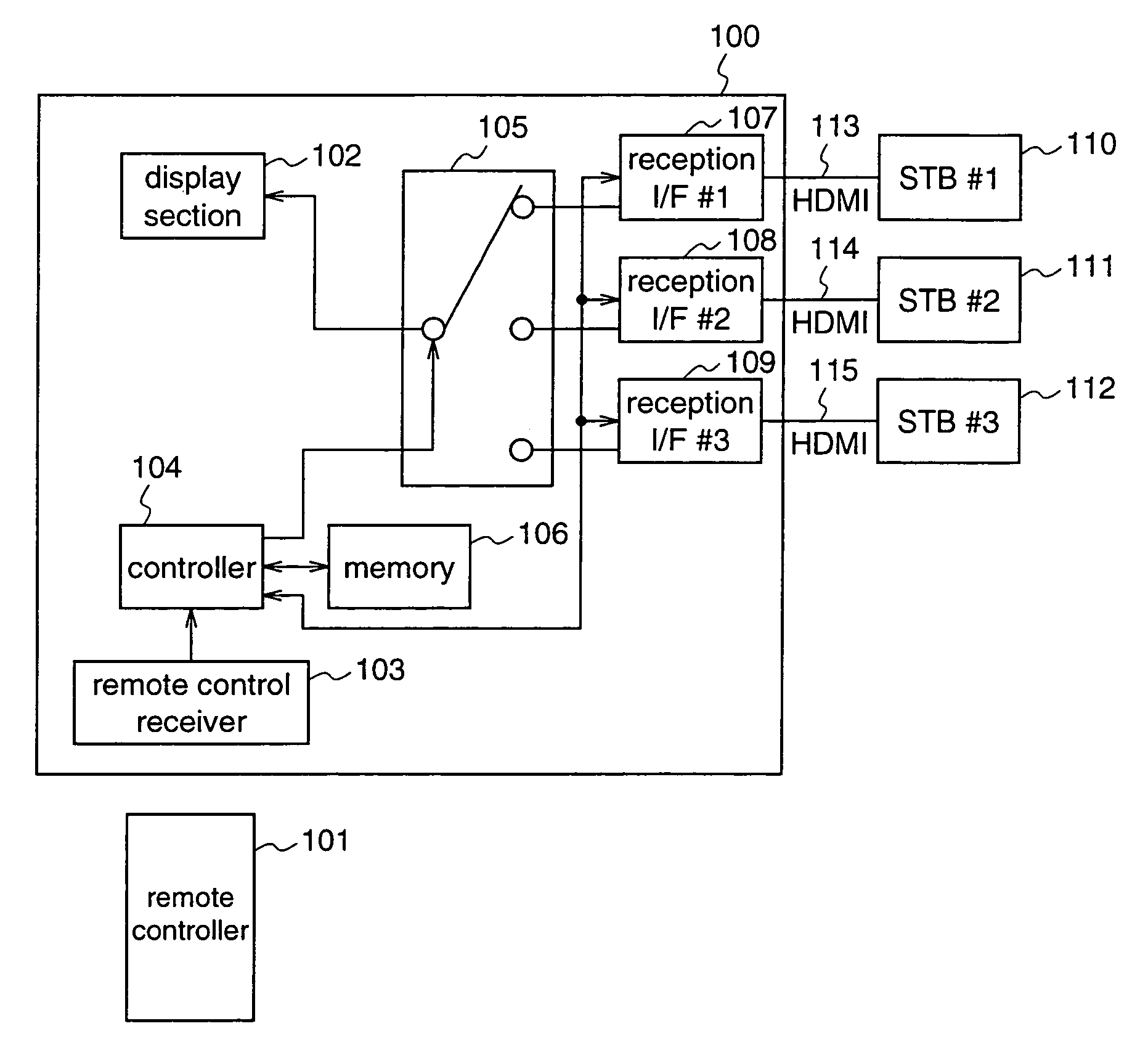
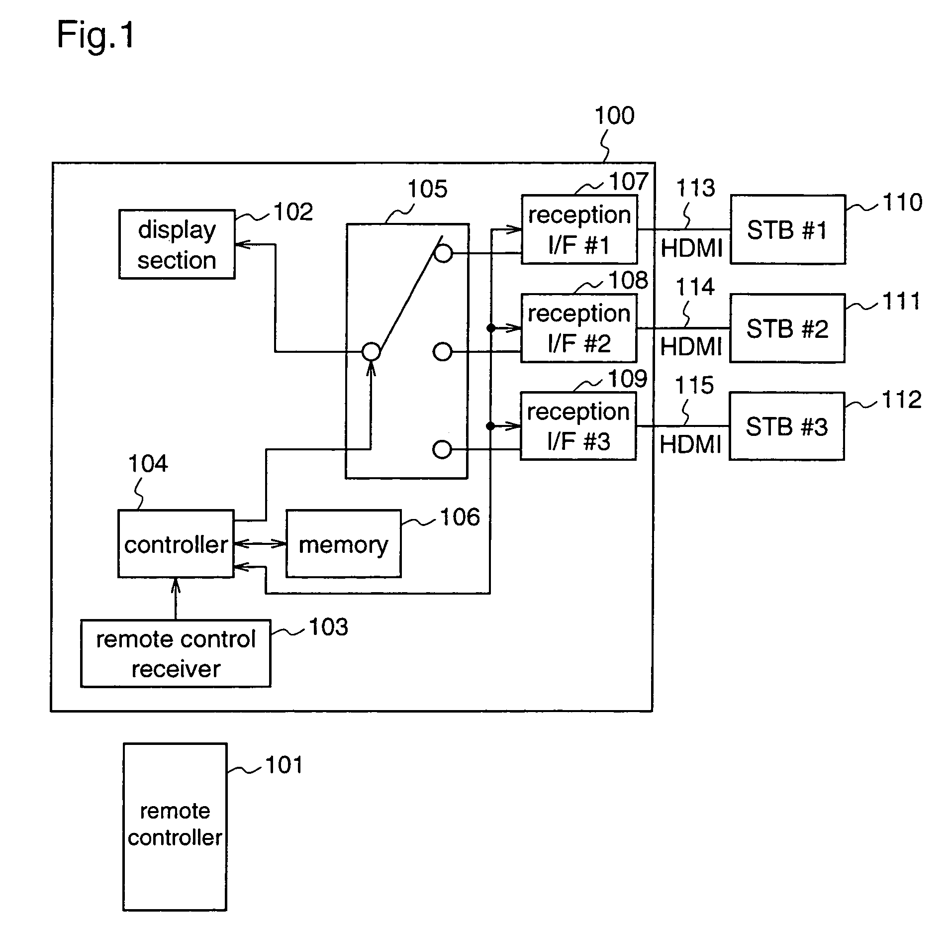
[0071]FIG. 1 is a block diagram illustrating the construction of the AV system according to the first embodiment.

[0072]In FIG. 1, reference numeral 100 denotes a display unit for displaying inputted video, and outputting audio. Reference numeral 101 denotes a remote controller associated with one of connected devices described later. Reference numeral 102 denotes a display section for displaying video and outputting audio, and preferably, the display section 102 comprises a CRT, or a liquid crystal panel, or a plasma display, and a speaker. Reference numeral 103 denotes a remote control receiver for receiving a signal outputted from the remote controller 101. Reference numeral 104 denotes a controller of the display unit 100, for controlling the whole display unit. Preferably, the controller 104 is a CPU. Reference numeral 105 denotes a selector for selecting video data and aud...

embodiment 2

[0100]Hereinafter, an AV system according to a second embodiment of the present invention will be described. This second embodiment is different from the first embodiment only in that the AV switch is separated from the display in this second embodiment while the function of the AV switch is included in the display in the first embodiment.

[0101]FIG. 9 is a block diagram illustrating the construction of the AV system according to the second embodiment. In FIG. 9, the same reference numerals as those shown in FIG. 1 denote the same or corresponding constituents.

[0102]Reference numeral 200 denotes a display for displaying inputted video, and outputting audio. In this second embodiment, the display 200 includes no AV switch. Reference numeral 201 denotes a remote controller that is associated with one of plural connected devices. Reference numeral 202 denotes a display unit for displaying video and outputting audio. Preferably, the display section 202 comprises a CRT, or a liquid crysta...

embodiment 3

[0126]Hereinafter, an AV system according to a third embodiment of the present invention will be described.

[0127]The construction of the AV system according to the third embodiment is identical to that of the first embodiment (refer to FIG. 1), and the function of the AV switch is included in the display.

[0128]The difference between the third embodiment and the first embodiment is as follows. While in the first embodiment the maker code and device code are transferred from the connected device such as an STB using the device control line of the HDMI, in this third embodiment the maker code and device code are put on a portion of a video blanking period and transferred from the STB.

[0129]Hereinafter, the first half of the processing flow (connected device recognition method) according to the third embodiment will be described with reference to FIG. 1. The first half of the processing corresponds to the process steps from when the STBs and the display are connected to when the maker c...


PUM


Abstract

On a display (100) end, maker codes and device codes are read from all STBs (110˜112) connected to the display (100) to create a connected-device table. When a user presses a button on a remote controller, the display receives a remote control code outputted from the remote controller, searches the connected-device table for a maker code and a device code that match the maker code and the device code included in the remote control code, controls a selector (105) so that a reception interface that is connected to an STB whose maker code and device code match those included in the remote control code is connected to a display section (102), thereby to display AV data transmitted from the STB on the display section (102).

Description

FIELD OF THE INVENTION[0001]The present invention relates to an audio visual system (hereinafter referred to as an “AV system”) for performing remote control operations using remote controllers corresponding to plural AV devices, when desired AV devices, such as STBs (Set Top Boxes), DVD (Digital Versatile Disk) players, DVD recorders, and VTRs, are connected to a display.BACKGROUND OF THE INVENTION[0002]FIG. 37 shows the construction of a conventional AV switcher (refer to Japanese Published Patent Application No. Hei.5-83646).[0003]In FIG. 37, reference numeral 1 denotes an AV switcher, numeral 2 denotes a key operation unit, numeral 3 denotes a light-receptive unit for receiving an optical remote control signal, numeral 4 denotes a waveform shaping circuit, numeral 5 denotes an EEPROM for holding the remote control signal, numeral 6 denotes a CPU, numerals 7˜10 denote N pieces of light-emitting units for converting the remote control signals outputted from the CPU 6 into infrared...

Claims


Application Information

Patent Timeline
Patent Type & Authority Patents(United States)
IPC IPC(8): H04N7/173G06F13/00H04N5/00H04N5/44H04Q9/00
CPCH04B1/202H04N5/44H04N5/765H04N21/4122H04N21/42204H04N21/42684H04N5/85H04N21/47
Inventor SUZUKI, HIDEKAZUNIO, YUTAKAYAMADA, MASAZUMINAGATA, KOICHIRO
Owner PANASONIC CORP
Why Eureka
Try Eureka