Exposure apparatus, and device manufacturing method

a technology of equipment and manufacturing method, applied in the direction of photomechanical equipment, instruments, printers, etc., can solve the problems of liquid spilling from space, margin shortage during the exposure operation, and small depth of focus

Active Publication Date: 2006-06-01
NIKON CORP
View PDF93 Cites 302 Cited by
  • Summary
  • Abstract
  • Description
  • Claims
  • Application Information

AI Technical Summary

Benefits of technology

[0023] The present invention was made under such circumstances, and has as its first object to provide an exposure apparatus that can

Problems solved by technology

If such a situation continues, the depth of focus may become so small that margin shortage may occur during the exposure operation.
However, in the case the immersion method above is merely applied to a projection exposure apparatus by the step-and-repeat method, the liquid spills from the space between the projection optical system and the wafer when the wafer is moved in between shots by a step movement to the exposure position for the next shot area after exposure of a shot area has been completed.
Therefore, the liquid has to be supplied again, and the recovery of the liquid could also be difficult.
However, in the invention disclosed in patent document 1 below, because the supply piping, the recovery piping, and the like are arranged outside the projection optical system, the degree of freedom is limited for peripherals such as sensors of various kinds like a focus sensor or an alignment sensor that have to be arranged around the projection optical system.
Especially when the space in between the projection optical system and the substrate is large, or in other words, the layer of liquid is thick, such temperature inclination or pressure inclination could be the cause of aberration such as inclination of image plane, which could lead to partial deterioration in the transfer accuracy of the pattern, which in turn could be the cause of deterioration in the line width uniformity of the transferred image of the pattern.
However, in this case, the space in between the projection optical system and the substrate beco

Method used


Image

  • Exposure apparatus, and device manufacturing method
  • Exposure apparatus, and device manufacturing method
  • Exposure apparatus, and device manufacturing method

Examples


first embodiment

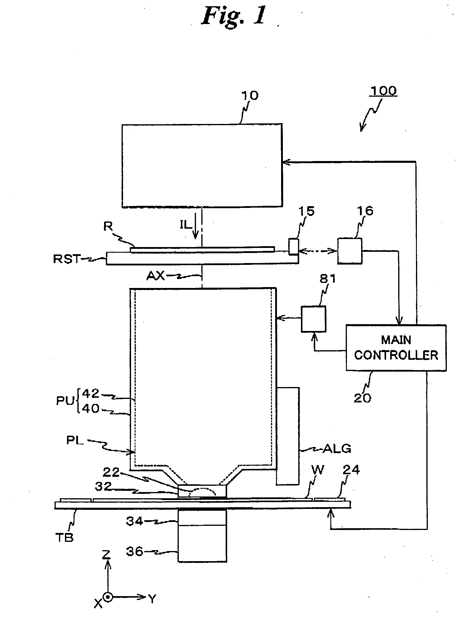
[0065] A first embodiment of the present invention will be described below, referring to FIGS. 1 to 6.

[0066]FIG. 1 shows the entire configuration of an exposure apparatus 100 related to the first embodiment. Exposure apparatus 100 is a projection exposure apparatus (the so-called scanning stepper) by the step-and-scan method. Exposure apparatus 100 is equipped with: an illumination system 10; a reticle stage RST that holds a reticle R serving as a mask; an optical unit PU; a wafer table TB that serves as a table on which a wafer W serving as a substrate is mounted; a main controller 20 that has overall control over the entire apparatus, and the like.

[0067] As is disclosed in, for example, Kokai (Japanese Unexamined Patent Publication) No. 2001-313250 and its corresponding U.S. Patent Application Publication No. 2003 / 0025890, illumination system 10 has an arrangement that includes parts such as a light source, an illuminance uniformity optical system that includes an optical integr...

modified example

[0151] In the description so far, the case has been described where hydrostatic pad 32 is fixed to barrel 40 and the position relation between projection optical system PL and hydrostatic pad 32 is constantly maintained. The present invention, however, is not limited to this, and for example, as the optical element that constitutes projection optical system PL closest to the image plane, a divided lens, which is vertically divided into two, as is shown in FIG. 8, may be used. Divided lens 150 in FIG. 8 is composed of a first segment lens 152a of a hemispheric shape arranged on the lower side, and a second segment lens 152b. Second segment lens 152b has an inside (inner surface), which is a spherical surface whose radius of curvature has the same center point as the outer surface (a part of the spherical surface) of the first segment lens 152a but is slightly larger than the radius of curvature of the first segment lens 152a, and an outside (outer surface), which is a spherical surfa...

second embodiment

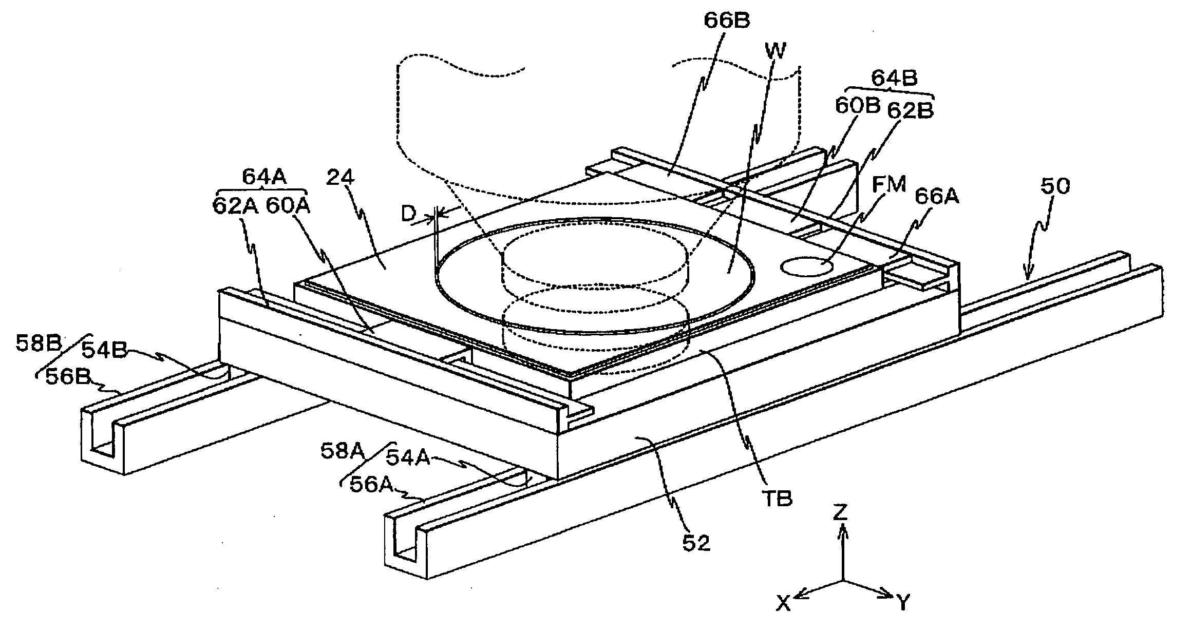
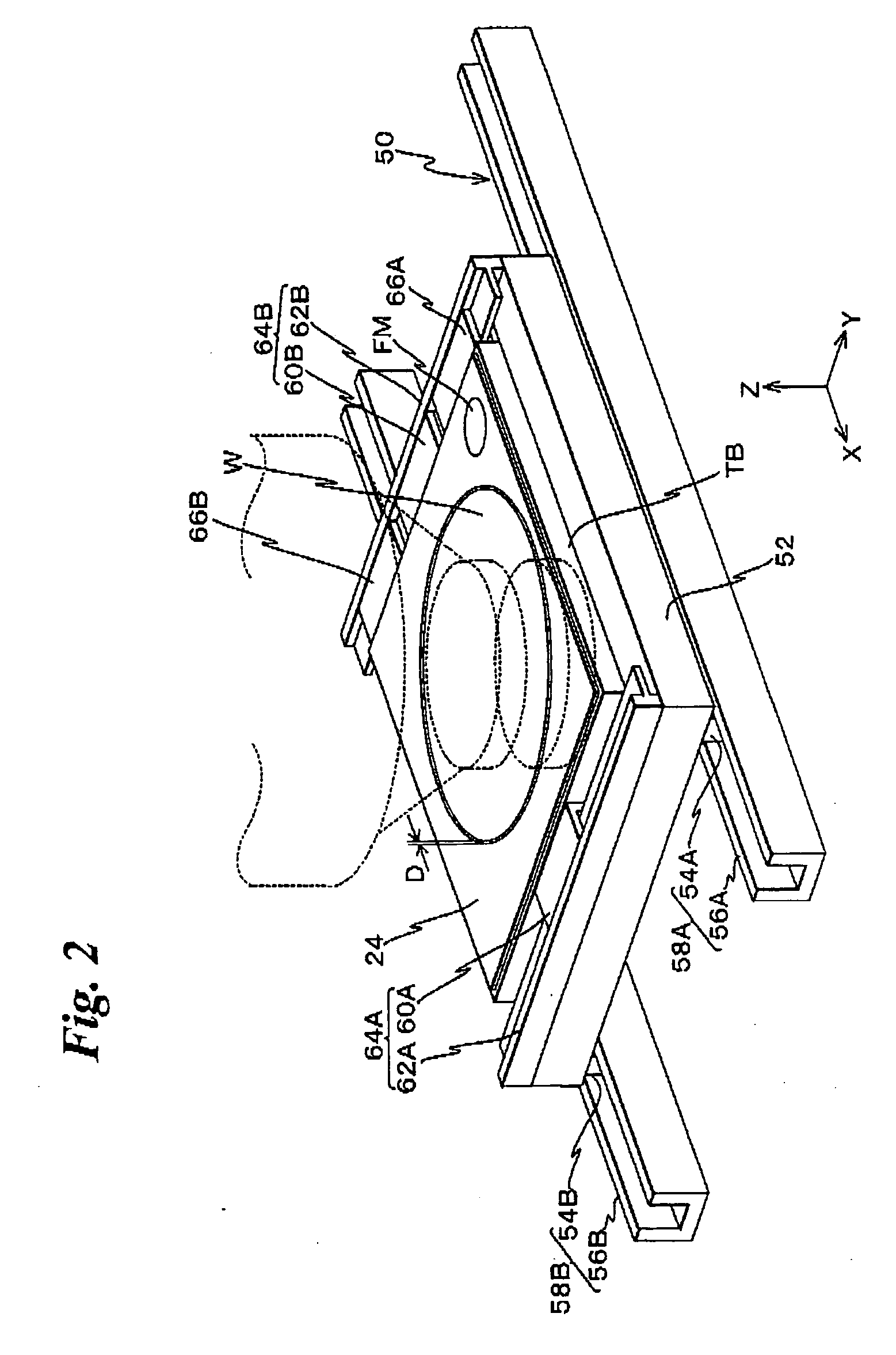
[0155] Next, an exposure apparatus of a second embodiment of the present invention is described, referring to FIGS. 9 and 10. FIG. 9 is a planar view showing a configuration of a wafer stage unit 300 that constitutes the exposure apparatus of the second embodiment. From the viewpoint of preventing redundant explanations, the same reference numerals will be used for parts that have the same or similar arrangement as the first embodiment previously described, and the description thereabout will be omitted.

[0156] In the exposure apparatus of the second embodiment, optical unit PU, and an alignment detection system ALG′ similar to alignment detection system ALG is disposed in the Y-axis direction spaced apart at a predetermined distance. And, below optical unit PU, drive unit 50 described earlier is disposed, and wafer W is to be mounted on a wafer table TB1 provided on stage 52, which constitutes drive unit 50. In addition, below an alignment detection system ALG′, an XY stage unit 18...


PUM

PropertyMeasurementUnit
Distanceaaaaaaaaaa
Pressureaaaaaaaaaa
Areaaaaaaaaaaa

Abstract

A hydrostatic bearing is provided opposite to a wafer on a table. The hydrostatic bearing maintains the distance between the bearing surface and the wafer in the direction of the optical axis of a projection optical system at a predetermined value.

Description

CROSS-REFERENCE TO RELATED APPLICATIONS [0001] This is a continuation of International Application PCT / JP2004 / 008595, with an international filing date of Jun. 18, 2004, the entire content of which is hereby incorporated herein by reference.BACKGROUND OF THE INVENTION [0002] 1. Field of the Invention [0003] The present invention relates to exposure apparatus, and device manufacturing methods, and more particularly to an exposure apparatus used in a lithography process where electronic devices such as semiconductor devices, liquid crystal display devices, or the like is manufactured, and a device manufacturing method that uses the exposure apparatus. [0004] 2. Description of the Related Art [0005] In a lithography process for producing electronic devices such as semiconductor devices (integrated circuits), liquid crystal display devices, or the like, projection exposure apparatus are used that transfer the image of a pattern formed on a mask or a reticle (hereinafter generally referr...

Claims


Application Information

Patent Timeline
IPC IPC(8): G03B27/58G03F7/20
CPCB82Y10/00G03F7/70325G03F7/70341Y10T29/49826G03F7/70733G03F7/70816G03F7/70716G03F7/2041H01L21/0274H01L21/0273H01L21/0275G03F7/70225G03F7/70333G03F7/70725G03F7/70758G03F7/20G03F7/70275G03F7/70775G03F7/202
Inventor EBIHARA, AKIMITSU
Owner NIKON CORP
Why Eureka
Try Eureka