Voltage conversion device and computer-readable recording medium with program recorded thereon for computer to execute control of voltage conversion by voltage conversion device

Inactive Publication Date: 2006-06-01
TOYOTA JIDOSHA KK
View PDF13 Cites 38 Cited by
  • Summary
  • Abstract
  • Description
  • Claims
  • Application Information

AI Technical Summary

Benefits of technology

[0060] Thus, any difference between a duty based on the voltage command value and an actual duty, which is caused by the dead time, can be reduced and, variation in output voltage of the voltage converter as well as variation in DC curren

Problems solved by technology

Therefore, the on-duty of the upper arm that is calculated based on the voltage command value is partially occupied by the dead time of the upper arm and thus the original on-duty cannot be ensured.
As a result, the power supply could be broken.
In addition, in a period in which a voltage step-up operation is performed, when the on-duty of

Method used


Image

  • Voltage conversion device and computer-readable recording medium with program recorded thereon for computer to execute control of voltage conversion by voltage conversion device
  • Voltage conversion device and computer-readable recording medium with program recorded thereon for computer to execute control of voltage conversion by voltage conversion device
  • Voltage conversion device and computer-readable recording medium with program recorded thereon for computer to execute control of voltage conversion by voltage conversion device

Examples


Example

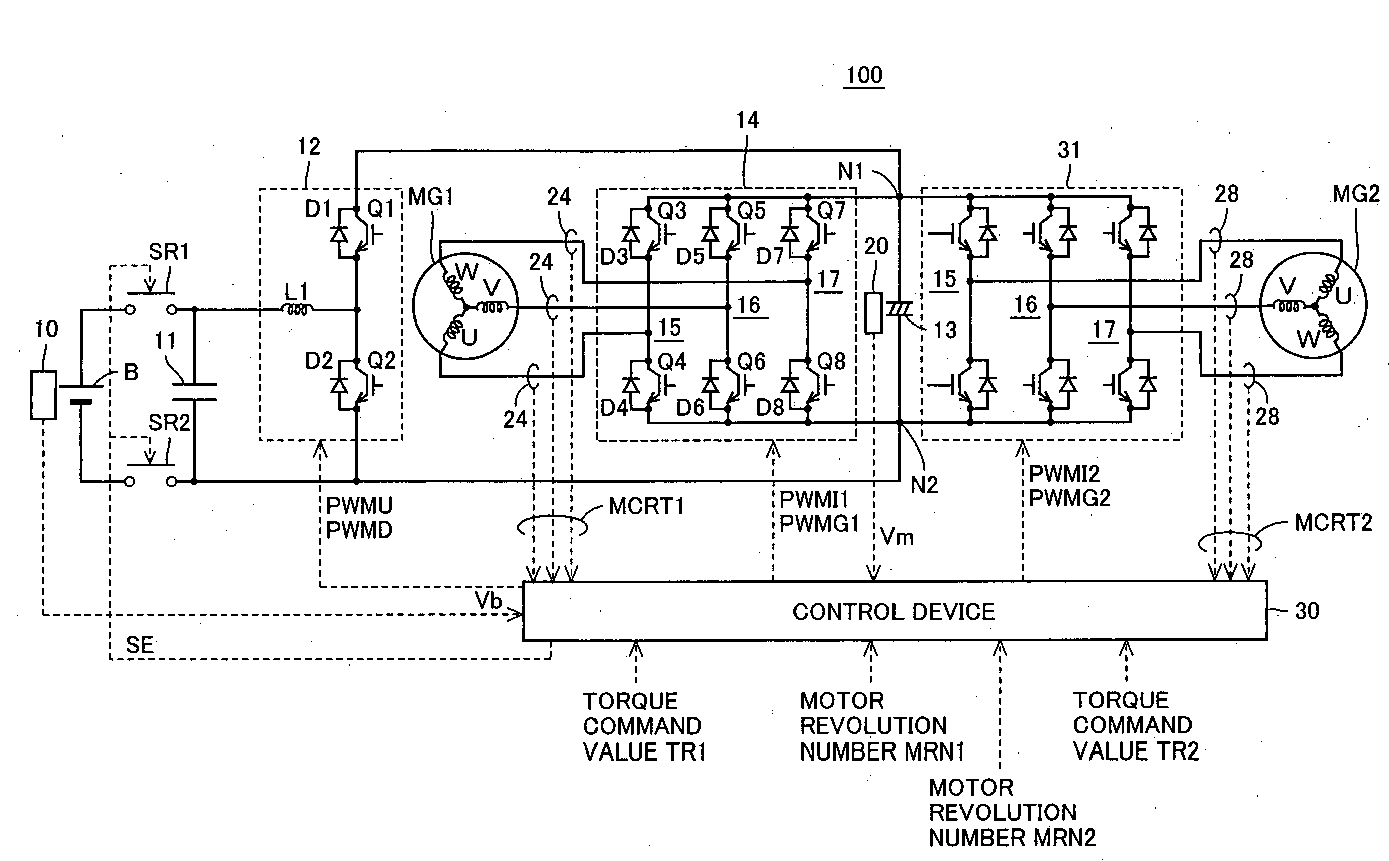
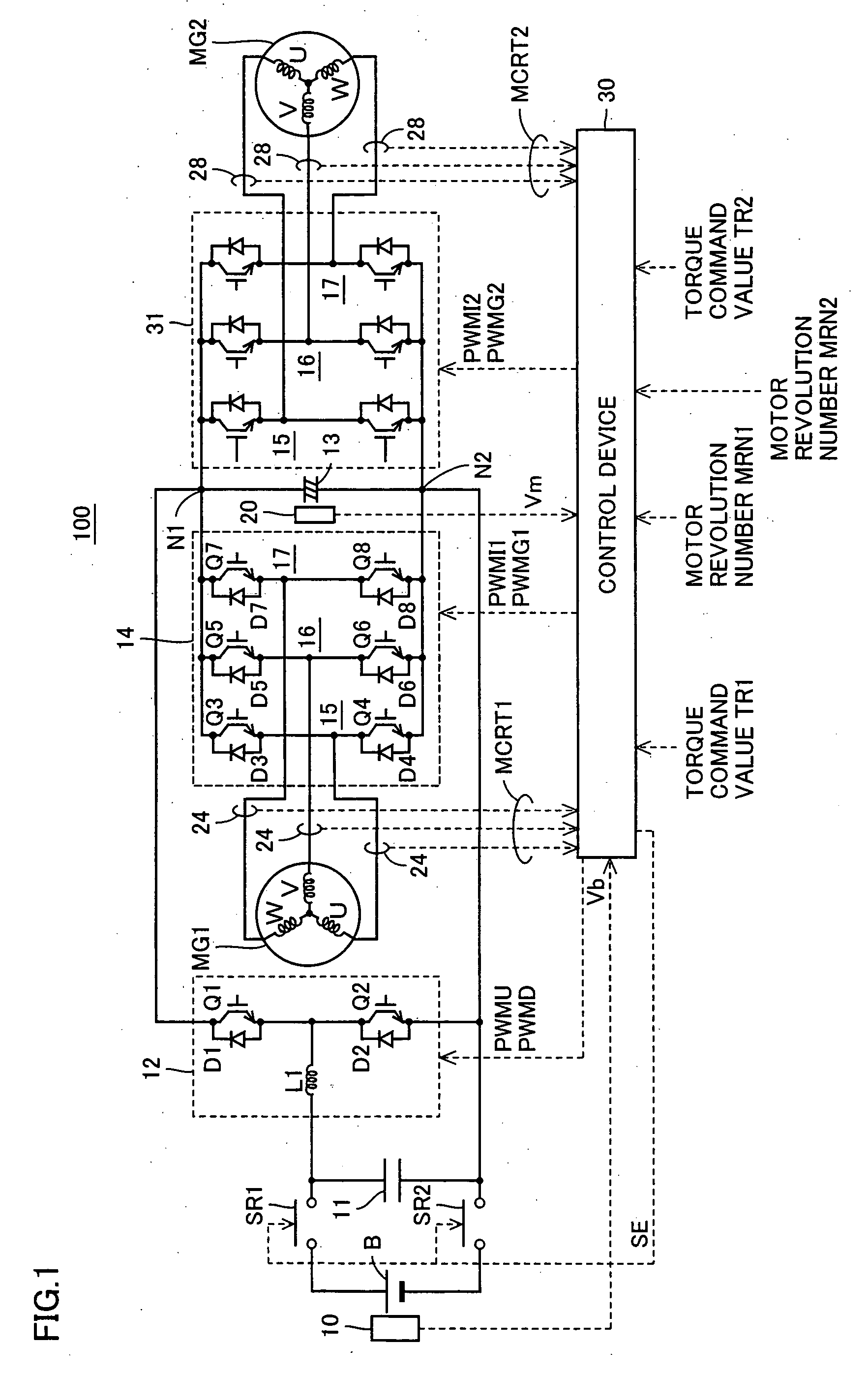
[0093]FIG. 1 is a schematic block diagram of a motor drive apparatus having a voltage conversion device according to a first embodiment of the present invention.

[0094] Referring to FIG. 1, motor drive apparatus 100 includes a DC power supply B, voltage sensors 10, 20, system relays SR1, SR2, capacitors 11, 13, a voltage step-up converter 12, inverters 14, 31, current sensors 24, 28, and a control device 30.

[0095] A motor generator MG1 is mounted for example on a hybrid vehicle. Motor generator MG1 is connected to an engine (not shown) of the hybrid vehicle to serve as an electric generator driven by the engine while serving as an electric motor for the engine, for example, capable of starting the engine. Control is performed for keeping the engine in an efficient operating state by adjusting power generation torque of motor generator MG1. Thus, favorable fuel economy and exhaust gas of the hybrid vehicle can be achieved.

[0096] A motor generator MG2 is mounted for example on a hyb...

Example

Second Embodiment

[0210] In the embodiment described above, in the case where on-duty D_ON—1 is influenced by dead time Dt, converter control means 302A to 302C make the transition to the state where the voltage step-up operation is stopped under the condition that it is determined DC power supply B will not be deteriorated. Accordingly, it is avoided that DC power supply B is damaged due to a sudden increase in DC current Ib in the transition to the state where the voltage step-up operation is stopped.

[0211] Alternatively, DC power supply B may be protected from the sudden increase (hereinafter also referred to as surge) of DC current Ib by allowing on-duty D_ON—1 to be controlled linearly.

[0212] Then, the present embodiment discloses a voltage conversion device capable of linearly controlling on-duty D_ON—1.

[0213]FIG. 9 is a functional block diagram of converter control means 302G of a motor drive apparatus according to the second embodiment of the present invention. Referring ...

Example

Third Embodiment

[0266] In connection with the first and second embodiments, it is described above that an example of the influence of dead time Dt on on-duty D_ON—1 is that the on-duty cannot linearly be controlled when on-duty D_ON—1 of the upper arm is in a region close to 1.0. A description is then given of a method of avoiding the resultant oscillations of output voltage Vm and DC current Ib.

[0267] Another example of the influence of dead time Dt on on-duty D_ON—1 is, as shown in FIG. 17, occurrence of an error between a calculated on-duty D_ON—1 and the on-duty at which NPN transistor Q1 is actually kept ON.

[0268]FIG. 17 shows a relation between on-duty D_ON—1 and the actual on-duty.

[0269] In FIG. 17, “discharge direction” refers to the direction in which DC voltage Vb that is stepped up by voltage step-up converter 12 in FIG. 1 is supplied to capacitor 13. In the discharge direction, DC current Ib flows through DC power supply B, reactor L1 and NPN transistor Q1 to a posit...


PUM


Abstract

A control device calculates a voltage command value of a voltage step-up converter based on a torque command value and a motor revolution number and calculates the on-duty of an NPN transistor based on the calculated voltage command value and a DC voltage from a voltage sensor. Under the conditions that the on-duty is influenced by a dead time and the DC voltage is smaller than a predetermined set value, the control device controls NPN transistors to step-up or step-down the voltage while fixing the on-duty at 1.0.

Description

[0001] This nonprovisional application is based on Japanese Patent Applications Nos. 2004-346991 and 2005-075624 filed with the Japan Patent Office on Nov. 30, 2004 and Mar. 16, 2005, respectively, the entire contents of which are hereby incorporated by reference. BACKGROUND OF THE INVENTION [0002] 1. Field of the Invention [0003] The present invention relates to a voltage conversion device and a computer-readable recording medium having a program recorded thereon for a computer to execute control of voltage conversion by a voltage conversion device. [0004] 2. Description of the Background Art [0005] Hybrid vehicles and electric vehicles have recently been of great interest as environment-friendly vehicles. A hybrid vehicle has, as its power sources, a DC (direct current) power supply, an inverter and a motor driven by the inverter in addition to a conventional engine. More specifically, the engine is driven to provide a power source and a DC voltage from the DC power supply is conv...

Claims


Application Information

Patent Timeline
IPC IPC(8): H02M7/5387B60L9/18H02M1/00H02M3/155
CPCH02M1/38Y02T10/6217H02M3/1588H02M7/53873H02M2001/0012H02P27/06H02P2201/09B60L7/14B60L11/123B60L11/14B60L11/1861B60L11/1868B60L15/007B60L15/2009B60L2210/14B60L2210/40B60L2240/12B60L2240/421B60L2240/423B60L2240/429B60L2240/441B60L2240/443Y02T10/7077Y02T10/7044Y02T10/7005Y02T10/7241Y02T10/7225Y02T10/7066Y02T10/7275Y02T10/644H02M3/157B60L50/61B60L50/16B60L58/20Y02T10/62Y02T10/64Y02T10/70Y02T10/72Y02T10/7072H02M1/0012
Inventor YAMADA, KENJISATO, EIJIOKAMURA, MASAKI
Owner TOYOTA JIDOSHA KK
Why Eureka
Try Eureka