Semi-automatic image quality adjustment for multiple marking engine systems

a marking engine and automatic technology, applied in the direction of instruments, electrographic process equipment, optics, etc., can solve the problems of affecting the lightness or darkness of a rendered or printed image, changing the toner concentration in the developer housing, and affecting the cost and physical space requirements of sensors and associated controls, so as to reduce the need for, or the effect of accuracy requirements

Inactive Publication Date: 2006-06-01
XEROX CORP
View PDF82 Cites 44 Cited by
  • Summary
  • Abstract
  • Description
  • Claims
  • Application Information

AI Technical Summary

Benefits of technology

[0017] For the foregoing reasons, there is a desire for methods and systems for calibrating, trimming, adjusting or fine tuning marking engine controls or setpoints, while eliminating or reducing the need for, or accuracy requirements of, at least some internal marking engine sensors.

Problems solved by technology

However, many factors, such as temperature, humidity, ink or toner age, and / or component wear, tend to move the output of a rendering or printing system away from the ideal or target output.
Therefore, changing the toner concentration in the developer housing may affect the lightness or darkness of a rendered or printed image.
However, these sensors and associated controls are associated with costs and physical space requirements.
However, over time, due to system wear and other sources of drift, the setpoints stored in the tables can become outdated or inappropriate.
While an observer might not ever notice the subtle variations when reviewing the output of either engine alone, when their output is compiled and displayed in the facing pages of a booklet the variation may become noticeable and be perceived by a printing services' customer as an issue of quality.
However, these Patents are not concerned with methods for improving or achieving image consistency between or among a plurality of marking engines.

Method used


Image

  • Semi-automatic image quality adjustment for multiple marking engine systems
  • Semi-automatic image quality adjustment for multiple marking engine systems
  • Semi-automatic image quality adjustment for multiple marking engine systems

Examples


Embodiment Construction

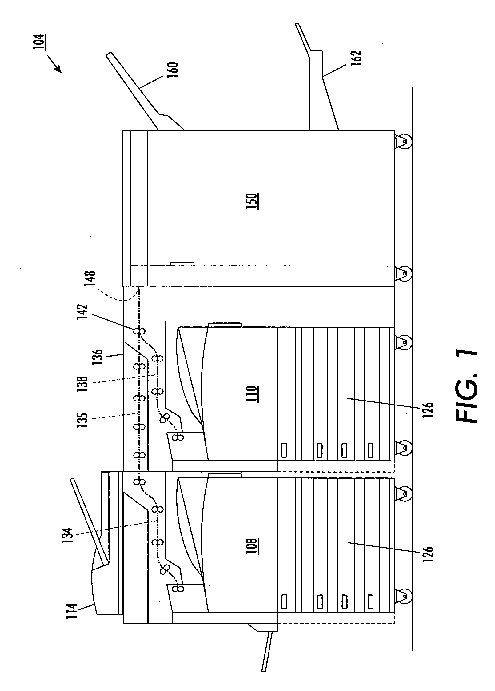
[0031] Referring to FIG. 1, a first document processing system 104, that might incorporate embodiments of the methods and systems disclosed herein, includes a first image output terminal (IOT) 108, a second image output terminal 110 and an image input device 114, such as a scanner, imaging camera or other device. Each image output terminal 108, 110 includes a plurality of input media trays 126 and an integrated marking engine (e.g., see FIG. 2 and related description below). The first IOT 108 may support the image input device 114 and includes a first portion 134 of a first output path. A second portion 135 of the first output path is provided by a bypass module 136. The second IOT 110 includes a first portion 138 of a second output path. A third portion of the first path and a second portion of the second path begin at a final nip 142 of the second IOT 110 and include an input to a finisher 150.

[0032] The finisher 150 includes, for example, first 160 and second 162 main job output...


PUM


Abstract

Using a document scanner or other image input device of an image or document processing system to periodically scan or image printed test images from a plurality of marking engines replaces internal sensors as a feedback means in image quality control. For example, image lightness (L*) is controlled by periodically printing mid-tone test patches, scanning the printed test patches with a main job document scanner and analyzing the scanned image to determine updated marking engine actuator set points. For instance, ROS exposure and/or scorotron grid voltages are adjusted to maintain image lightness consistency between marking engines.

Description

BACKGROUND [0001] There is illustrated herein in embodiments, methods and systems for adjusting image quality or image consistency in multiple printing or marking engine systems. Embodiments will be described in detail with reference to electrophotographic or xerographic print engines. However, it is to be appreciated that embodiments associated with other marking or rendering technologies are contemplated. [0002] It is desirable, in the use of any system, for an output of the system to match some target or desired output. For instance, in image rendering or printing systems, it is desirable that a rendered, or printed, image closely match, or have similar aspects or characteristics to, a desired target or input image. However, many factors, such as temperature, humidity, ink or toner age, and / or component wear, tend to move the output of a rendering or printing system away from the ideal or target output. For example, in xerographic marking engines, system component tolerances and ...

Claims


Application Information

Patent Timeline
Patent Type & Authority Applications(United States)
IPC IPC(8): G03G15/00
CPCG03G15/5062G03G2215/00021G03G15/0194G03G2215/00067G03G2215/0161G03G2215/00063
Inventor GRACE, ROBERT E.MONGEON, MICHAEL C.GRIFFITH, HUGH W.LESS, KRZYSZTOF J.ENSKAT, TIM D. M.
Owner XEROX CORP
Why Eureka
Try Eureka