Ear fixed type conversation device

a communication device and fixed type technology, applied in the field of ear fixed type conversation devices, can solve the problems of not a few users experiencing that they have difficulty in doing such things smoothly, no improvement in the calling style of holding a transmitter/receiver handset by hand, and restricted actions during talking on the phone, etc., to achieve the effect of reducing the electromagnetic wave effect, reducing the center of gravity, and stably attaching the communication device to the user

Inactive Publication Date: 2006-06-08
TOKIN CORP
View PDF18 Cites 68 Cited by
  • Summary
  • Abstract
  • Description
  • Claims
  • Application Information

AI Technical Summary

Benefits of technology

[0035] It is preferred that the main body further has a battery, and the battery is placed between the antenna and a user's head in a state where the communication device is attached to the user. The battery shields the electromagnetic wave generated in the electronic circuit substrate in this structure, and it is thereby possible to reduc

Problems solved by technology

Though conventional techniques have thus achieved improvement of distance freedom in mobile phones and PHS, no improvement has been made in calling style of holding a transmitter/receiver handset by hand to talk, which has been an issue from the start of development of phones.
Therefore, there is a problem that actions during talking on the phone, such as taking notes and checking documents, are restricted.
Not a few users would experience that they have difficulty doing such things smoothly during talking on the phone since only one hand is available.
However, since this technique requires to set a microphone part stably at the mouth of a user, a setting structure should be large.
Further, it is technically difficult to achieve a support mechanism for stable setting.
Therefore, in order to set the microphone part stably at the user's mouth, the user needs to use both hands and takes time to attach it.
Thus, a time delay occurs in the process of receiving a call signal, attaching a mech

Method used


Image

  • Ear fixed type conversation device
  • Ear fixed type conversation device
  • Ear fixed type conversation device

Examples


Embodiment Construction

[0053] An embodiment of the present invention is described hereinafter with reference to the drawings.

[0054] The embodiment of the present invention is described by referring to FIG. 14 showing each part of the human ear in addition to the figures showing the structure of a communication device or the like.

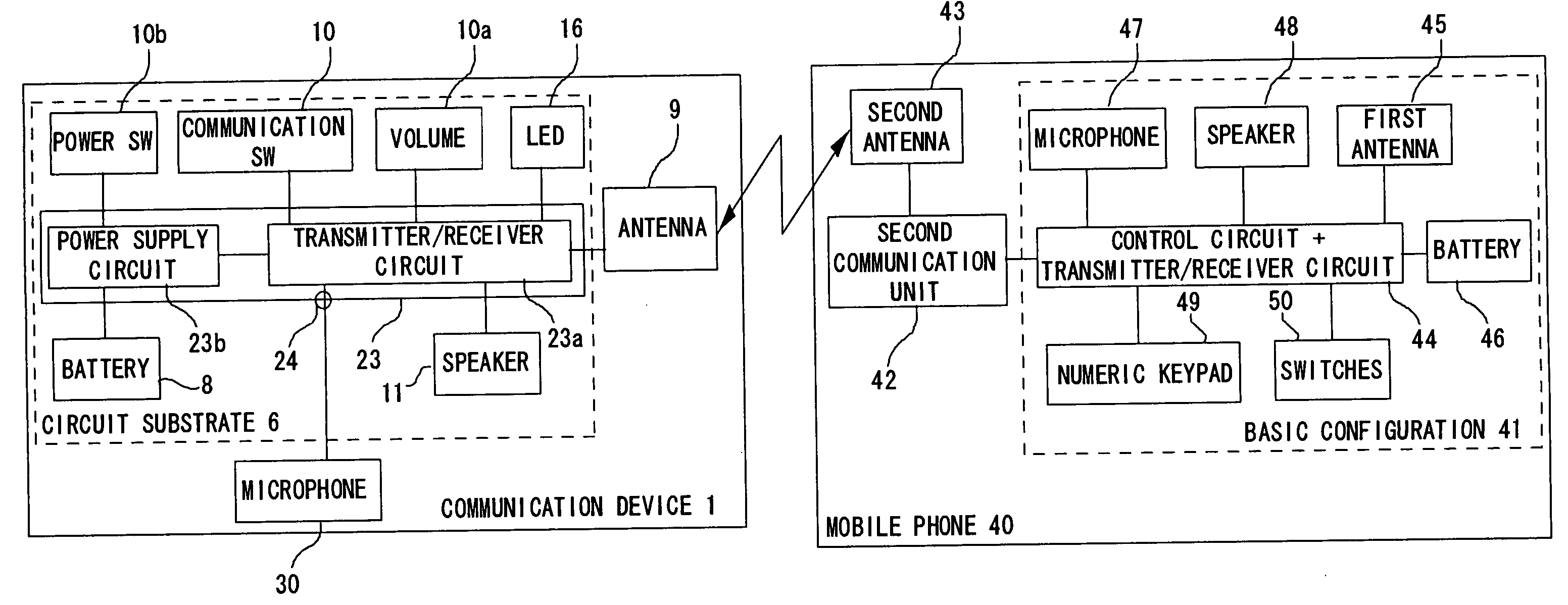
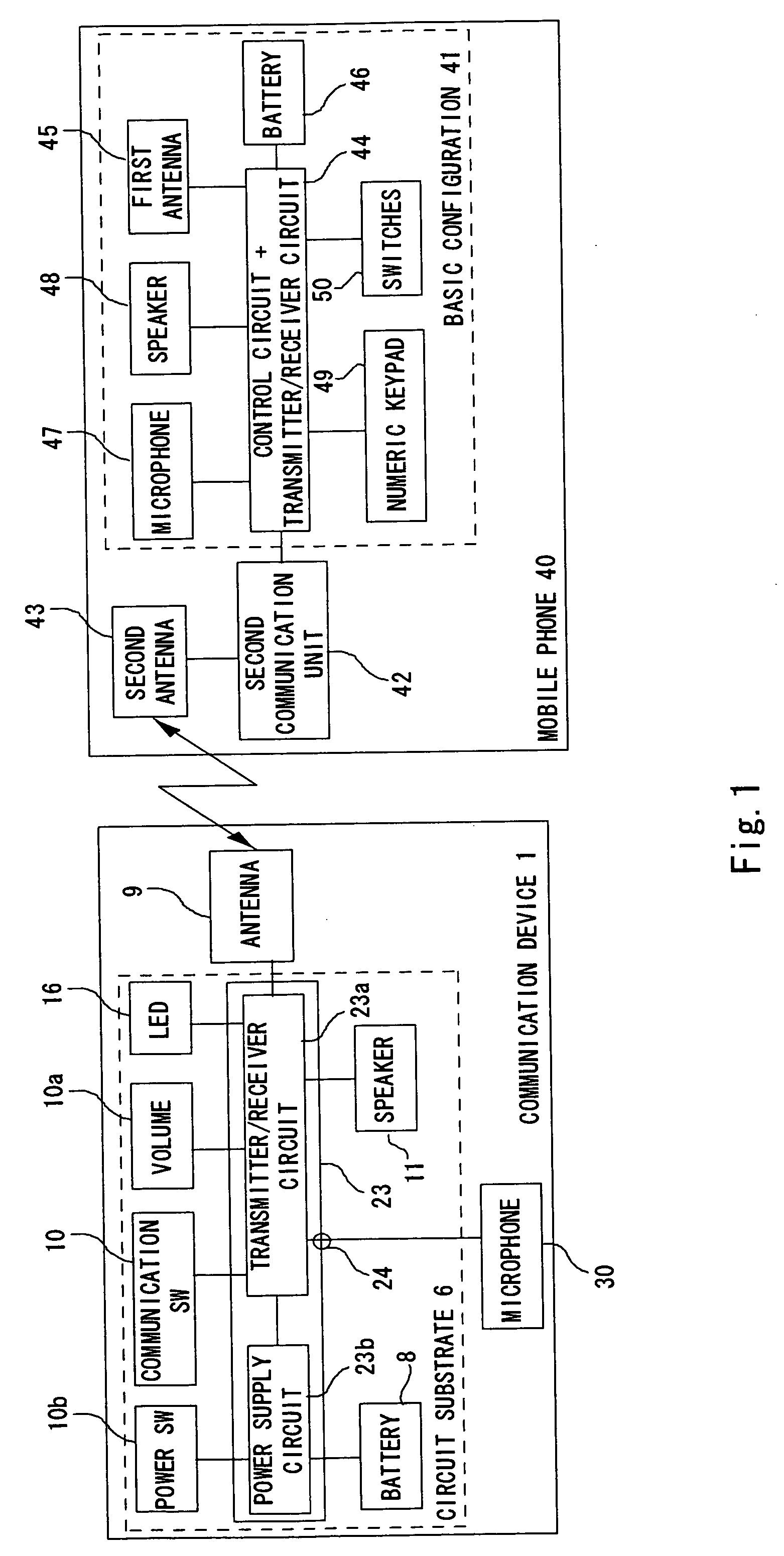
[0055] As shown in FIG. 1, an earset communication device 1 is used in combination with a mobile phone 40 as a main phone of the communication device 1. Instead of the mobile phone 40, the main phone of the communication device 1 may be various communication devices such as a fixed telephone and a telephone device using PC or PDA as platform. The functions relating to the communication between the main phone and the communication device 1 are substantially equal in the configuration using any of these devices.

[0056] As shown in FIG. 1, the communication device 1 has a circuit substrate 6, an antenna 9, and a microphone 30. The circuit substrate 6 has a signal circuit 23, a batt...


PUM


Abstract

An earset communication device capable of reliably suppressing transmission of microvibration to a microphone part. The earset communication device of the present invention is an earset communication device 1 attached to a human ear, which has a main body 2, a sound guide part 3 where a sound guide housing 3a protruding from the main body 2 is attached to the cavum conchae 61, and a microphone part 4 where a microphone housing 4a protruding from the main body 2 in continuously to the sound guide housing 3a in a fork shape is inserted into the cavum conchae in contact therewith. The main body 2 has a speaker 11. The sound guide part 3 has a sound guide tube 12 for guiding the sound output from the speaker 11 to the cavum conchae 61 in the sound guide housing 3a. The microphone part 4 has a bone conduction microphone 30 in the microphone housing 4a.

Description

TECHNICAL FIELD [0001] The present invention relates to an earset communication device. BACKGROUND ART [0002] Conventional mobile voice communication devices using radio communication technology have been developed under the main theme of “providing communication opportunities anytime and anywhere necessary”. Therefore, as shown in usage patterns of mobile phones and personal handy phone systems (PHS), mobile phones and PHS have a portable size allowing a user to put in a bag or pocket to carry. Further, as devices become smaller and portability increases, they come into wide use from certain users to general users. [0003] Recently, fixed telephones at homes and offices have cordless terminals. Though users had to talk on the phone within a cable length range, they are now free from distance and able to talk in places far from the telephone. It also becomes possible to talk on the phone while moving freely in homes and offices. Thus, freedom in communication increases in home and of...

Claims


Application Information

Patent Timeline
IPC IPC(8): H04R25/00H04B1/38H04B1/3822H04M1/03H04M1/05H04M1/60H04R1/00H04R1/10H04W84/10H04W92/08
CPCH04M1/05H04M1/6041H04R1/1016H04R1/1025H04R1/105H04R1/46H04R2201/107H04R2460/13
Inventor TANAKA, MASATOSHIFUJITA, MASAHIKOINAMURA, YOSHIAKI
Owner TOKIN CORP
Why Eureka
Try Eureka