Image forming apparatus
a technology of image forming apparatus and forming apparatus, which is applied in the direction of electrographic process apparatus, instruments, optics, etc., can solve the problems of uneven concentration of toner particles, difficulty in speeding up the forming of images, and increased size and cost of tandem types
- Summary
- Abstract
- Description
- Claims
- Application Information
AI Technical Summary
Benefits of technology
Problems solved by technology
Method used
Image
Examples
first embodiment
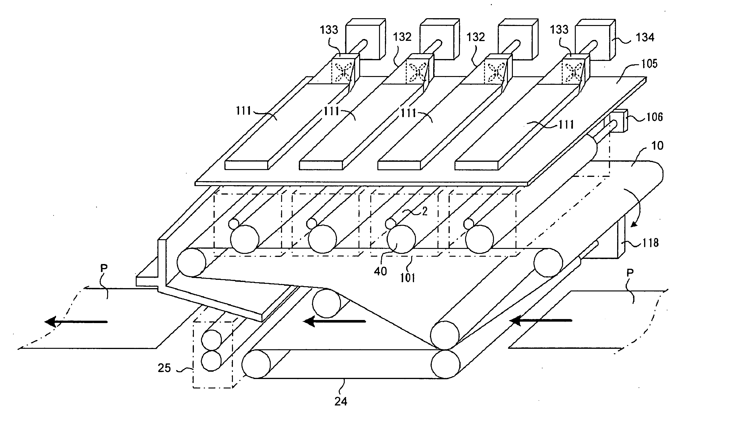
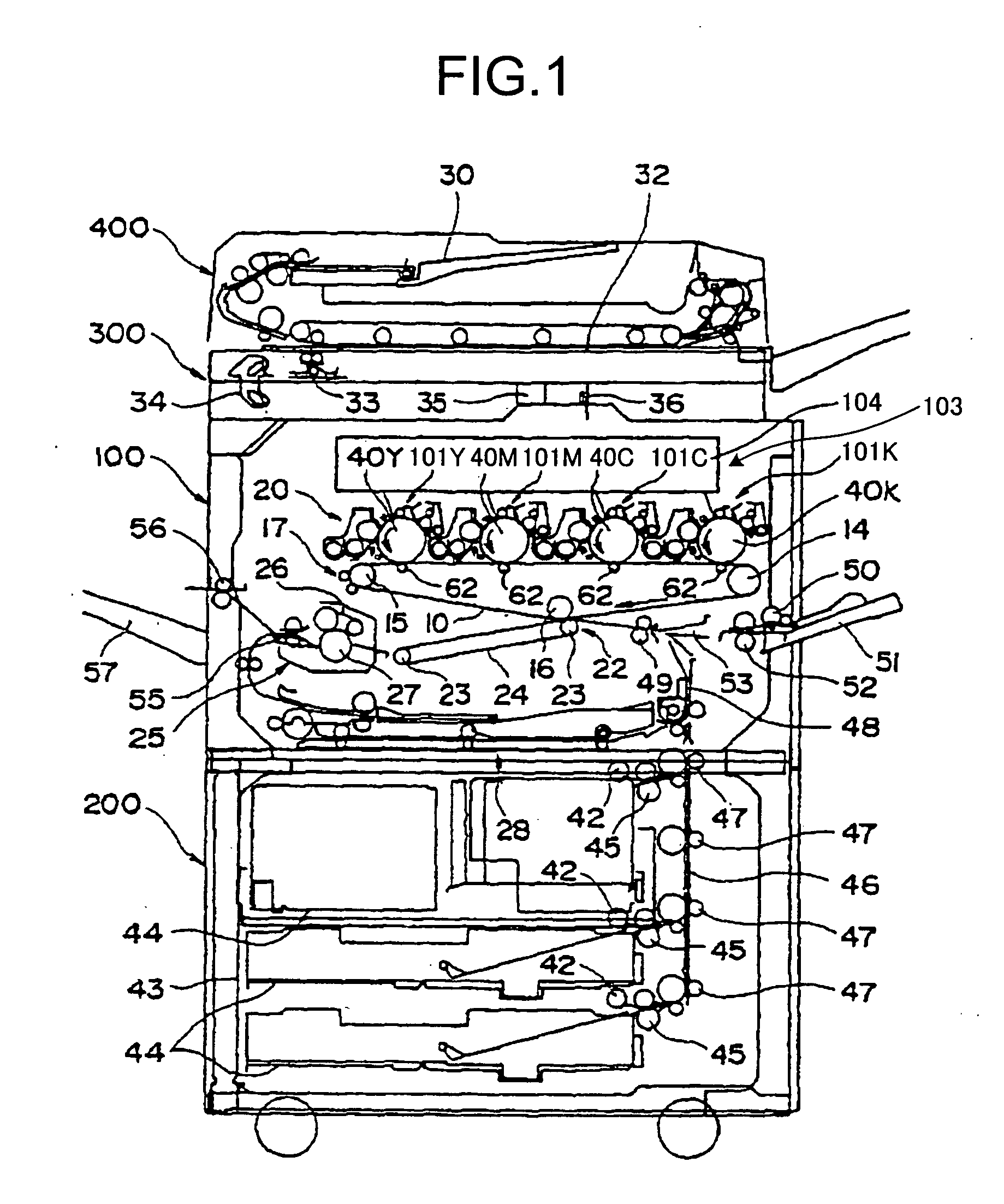
[0043] Exemplary embodiments according to the present invention will be explained in detail with reference to the accompanying drawings. FIG. 1 is a schematic of a copying machine according to the present invention. As shown in FIG. 1, the copying machine includes the main unit 100 and a paper feeding unit (a paper feed table) 200 on which the main unit is placed. Reference numeral 300 denotes a scanner mounted on the main unit 100, and reference numeral 400 denotes an automatic document feeder (ADF) provided above the scanner 300. The copying machine is an electrophotographic copying machine of a tandem type adopting an intermediate transfer (indirect transfer) system.
[0044] The main unit 100 includes an intermediate transfer belt 10 that is an intermediate transfer member serving as an image carrier at a central portion thereof. The intermediate transfer belt 10 is spanned around three supporting rollers 14, 15, and 16 serving as supporting and rotating members, and it is rotation...
second embodiment
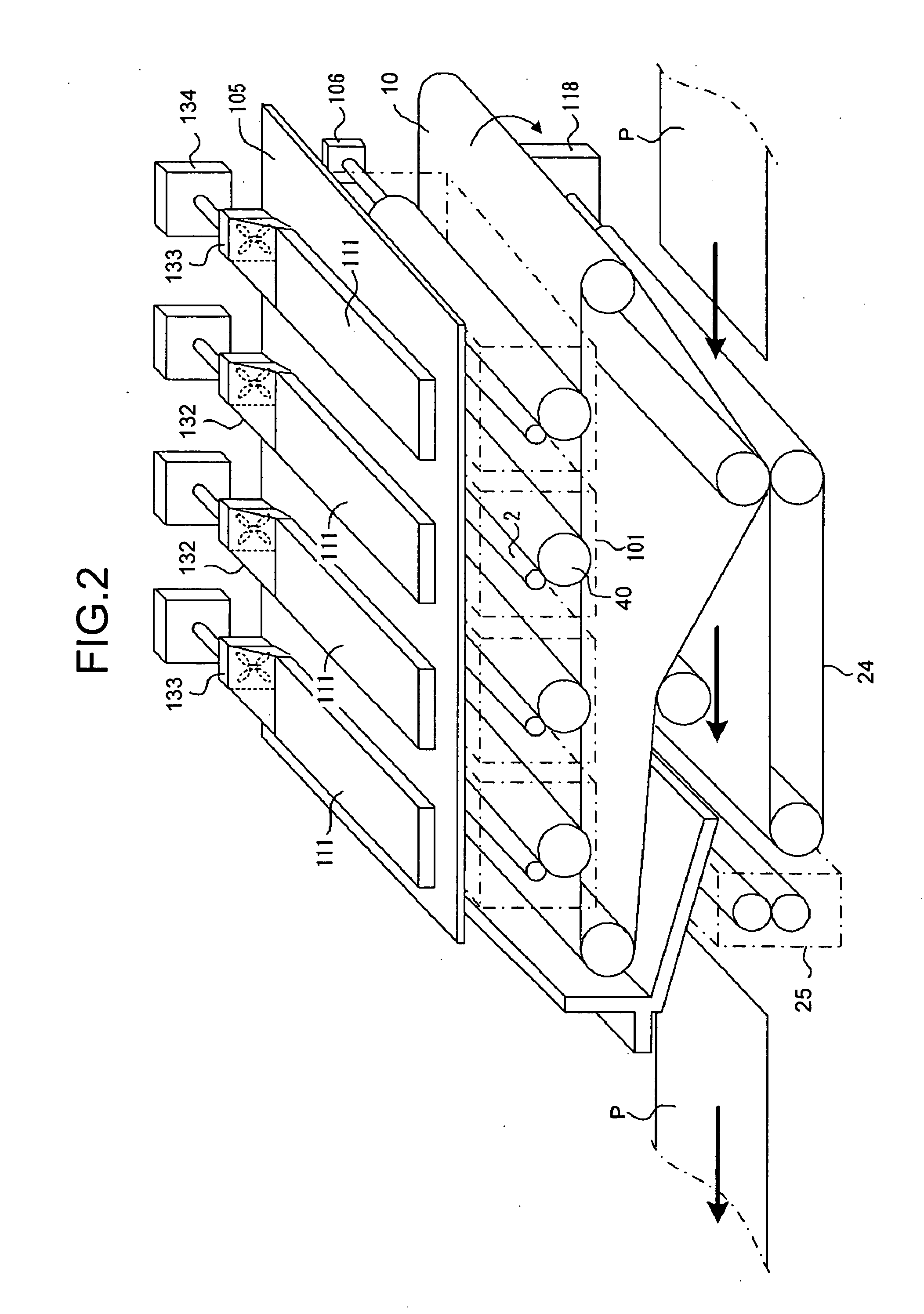
[0082]FIG. 11 is a plan view of the ducts in the copying machine according to the As shown in FIG. 11, the common duct 113 is provided to extend in a widthwise direction of the apparatus (left and right directions in FIG. 9 and FIG. 11) and it is connected to the exhaust fan 114 at one end thereof. Thus, when the exhaust fan 114 is rotated, hot air generated in the imaging unit 101 passes through the heat exhaust hole 110 provided in the unit frame 105 (arrow Z in FIG. 10) and passes through the common duct 113 from the heat exhaust duct 111 (arrows Y and X in FIG. 10) to be exhausted outside the copying machine by the exhaust fan 114. In the embodiment, heat generated in the imaging unit 101 mainly comes from self-heating at the developing unit (heat generated by friction occurring among developers in the developing element).
[0083] In a compact apparatus adopting a tandem system in which a plurality of (four) imaging units are arranged in parallel and the optical writing device 10...
third embodiment
[0109] According to the copying machine of the third embodiment, a vertical sectional shape of the heat exhaust duct 111 for exhausting heated air within each imaging unit 101 is set such that a horizontal length thereof is longer than a vertical length thereof. Specifically, the heat exhaust duct 111 has a vertical sectional shape in which a height thereof is 5 millimeters or less and a vertical sectional area thereof is 100 square millimeters or more.
[0110] Thus, the heat exhaust duct 111 can be set to have a sectional area (100 square millimeters or more) that allows suction of a sufficient amount of heated air for lowering temperature inside the imaging unit 101 while suppressing the height of the heat exhaust duct 111. As a result, the arrangement position of the optical writing device 103 can be suppressed from being higher than that in the conventional image forming apparatus, and the temperature inside the imaging unit 101 can be lowered sufficiently. The heat exhaust ducts ...
PUM
 Abstract
Description
Claims
Application Information
 - R&D
- Intellectual Property
- Life Sciences
- Materials
- Tech Scout
- Unparalleled Data Quality
- Higher Quality Content
- 60% Fewer Hallucinations
Browse by: Latest US Patents, China's latest patents, Technical Efficacy Thesaurus, Application Domain, Technology Topic, Popular Technical Reports.
© 2025 PatSnap. All rights reserved.Legal|Privacy policy|Modern Slavery Act Transparency Statement|Sitemap|About US| Contact US: help@patsnap.com


