Ink cartridge

a technology of ink cartridges and compression springs, applied in printing and other directions, can solve the problems of affecting the quality of ink cartridges, the inability to discard ink cartridges, and the inability to prevent and achieve the effect of preventing the leakage of ink

Inactive Publication Date: 2006-06-15
BROTHER KOGYO KK
View PDF7 Cites 18 Cited by
  • Summary
  • Abstract
  • Description
  • Claims
  • Application Information

AI Technical Summary

Benefits of technology

[0012] This invention has been developed in view of the above-described situations and it is therefore an immediate object of the invention to provide an ink cartridge including a valve member which can maintain functioning even when the valve member is pushed by an amount larger than a normal amount or in a direction different from a normal direction, in order to prevent leakage of ink from the ink cartridge and evaporation of water and other components from the ink.

Problems solved by technology

However, in the ink cartridge described above, the displacement of the valve member is realized by use of the compression spring, and thus an internal structure of the ink cartridge using the compression spring is complex.
Further, the compression spring is of metal and the ink cartridge can not be discarded as it is.
That is, upon disposal of a used ink cartridge, the compression spring should be detached from the ink cartridge to be discarded separately from the other part of the ink cartridge, thereby pushing up the cost of the disposal.
However, a user may attach the ink cartridge to the recording apparatus in an improper manner or tamper with the ink cartridge, such that the valve member is pushed by an amount larger than a normal amount by which the valve member is expected to be pushed, or in a direction different from a normal direction in which the valve member is expected to be pushed.
In the event of this, the side wall portion of the biasing member is stretched excessively, or the engaging portion is deformed into an irregular shape by locally deforming more at a part than the other part, resulting in disengagement of the valve member from the engaging portion of the biasing member, that is, the valve member gets out of the biasing member into the above-mentioned space and become incapable of getting back to a position to close the ink passage in a valve chamber defined inside the biasing member.
This causes leakage of the ink from the ink cartridge and evaporation of water or other components from the ink.

Method used


Image

  • Ink cartridge
  • Ink cartridge
  • Ink cartridge

Examples


first embodiment

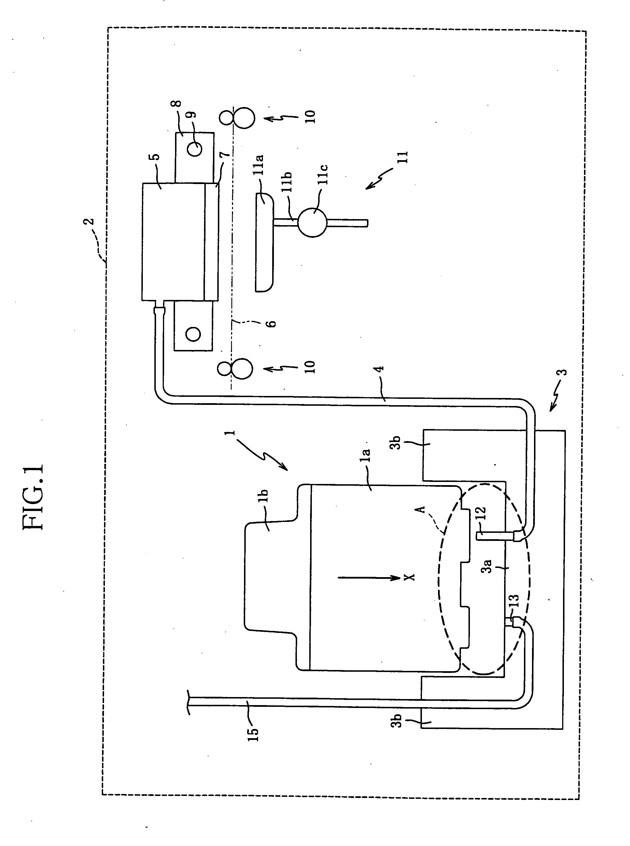
[0033] Referring to FIGS. 1 to 7, there will be described an ink cartridge according to the In a schematic view of FIG. 1, reference numerals 1 and 2 denote the ink cartridge and an inkjet recording apparatus to which the cartridge is attached.

[0034] The ink cartridge 1 is removably attachable to the ink jet recording apparatus 2 including a printhead 7 for ejecting ink droplets, and stores ink to be supplied to the printhead 7.

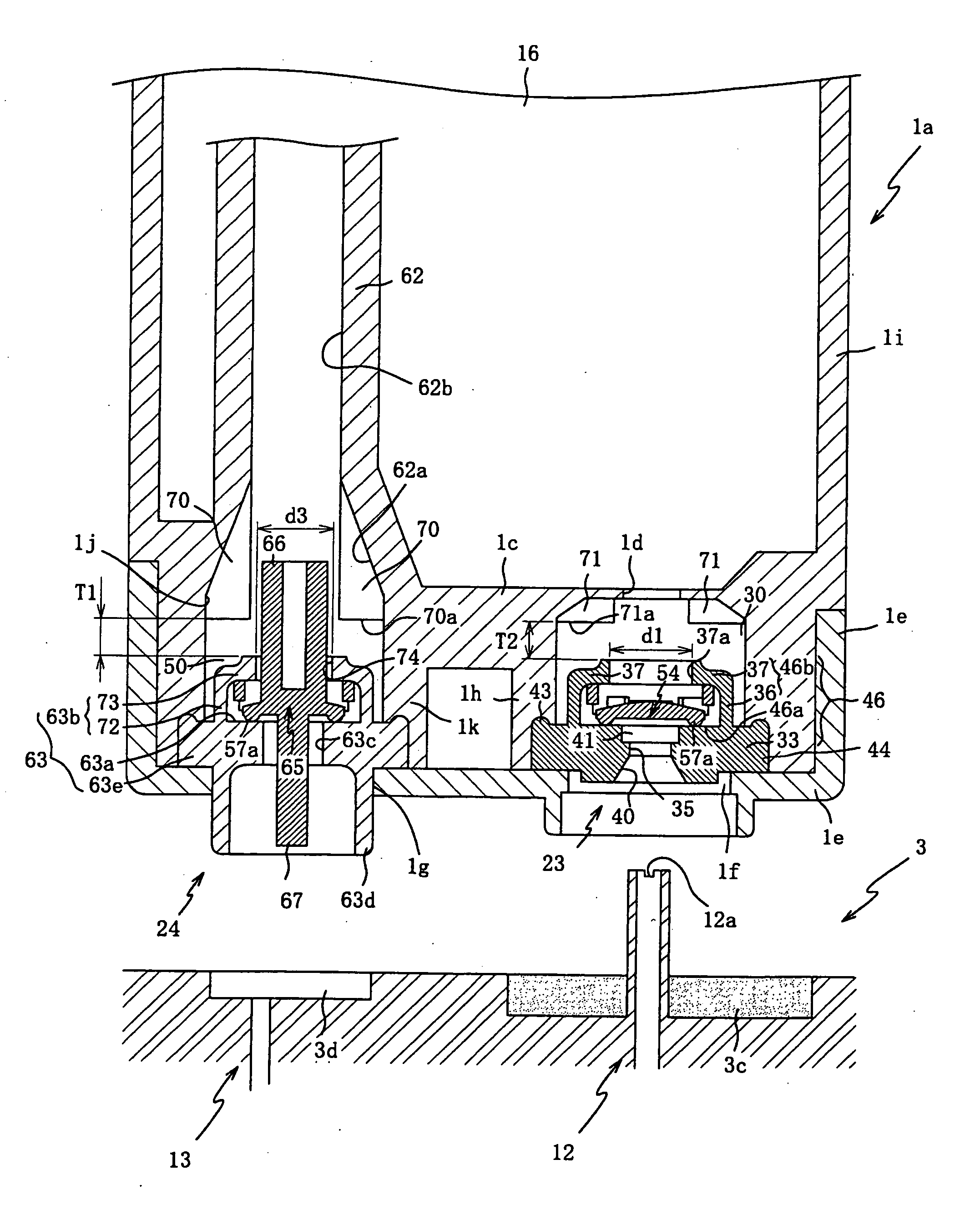
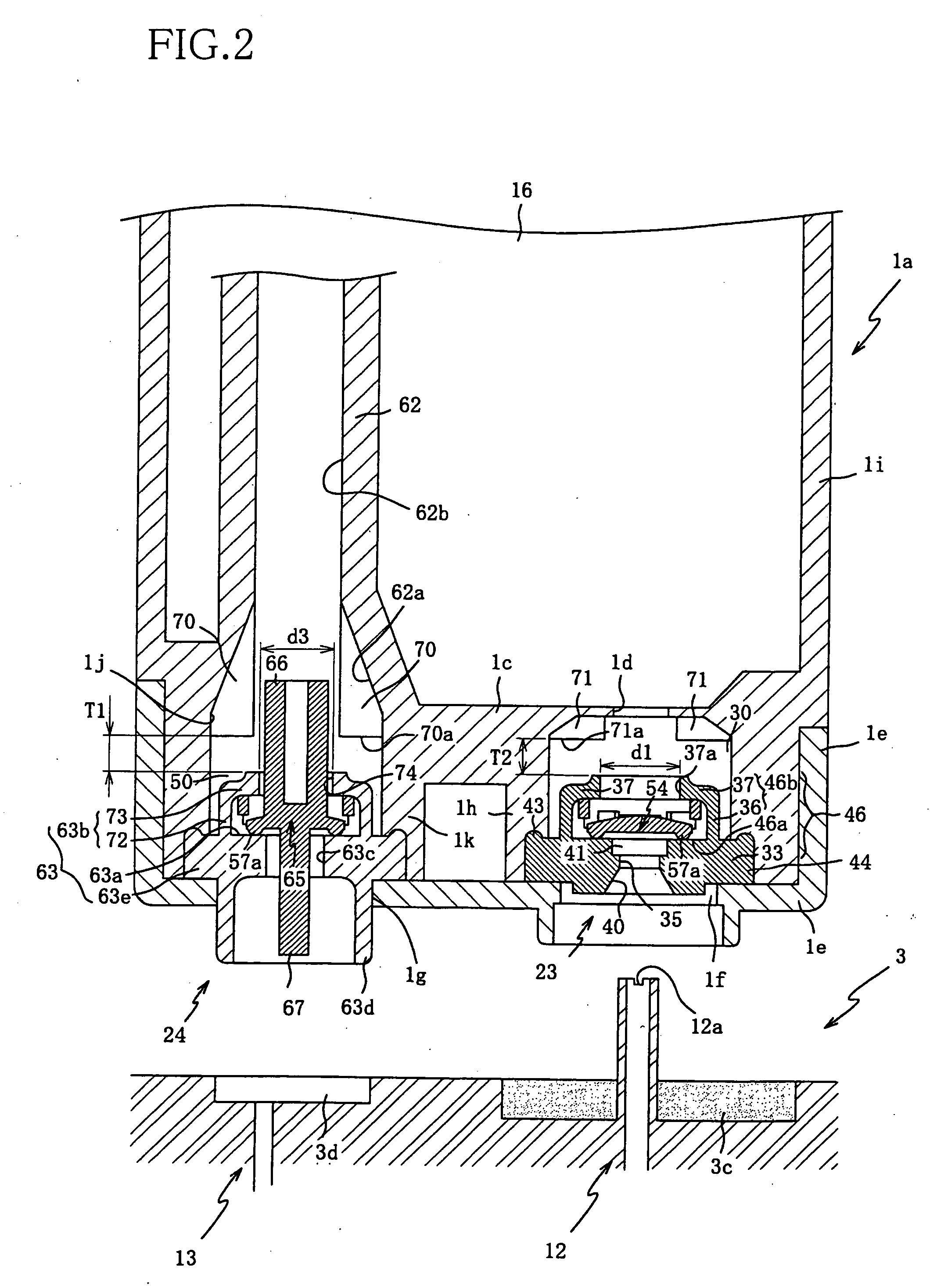
[0035] The ink cartridge 1 includes a casing 1a which is a hollow box-like member open in its upper side, and a lid 1b closing the upper open side of the casing 1a. The ink to be supplied to the printhead 7 is stored in an ink chamber 16 (shown in FIG. 2) in the casing 1a. A plurality of the ink cartridges 1, each containing ink of one of four colors, namely, cyan, magenta, yellow, and black, are attached to the inkjet recording apparatus 2.

[0036] The inkjet recording apparatus 2 includes a mounting portion 3 at which each ink cartridge 1 is removably atta...

second embodiment

[0083] since the air communication chamber has an internal passage communicating with the ink chamber, at a position to allow the valve member to enter in the internal passage when the valve member is pushed upward, the valve member, and a guiding portion constituted by the inner surface of the internal passage cooperates with the guide bar to constitute a guide device, an internal structure of the ink cartridge is simplified.

[0084] According to the ink cartridge of the second embodiment, a limiter is constituted by a surface (namely, the ceiling surface of the air communication chamber and the ink communication chamber) with which the engaging portion is brought into contact before the valve member disengages from the engaging portion. That is, that surface can serve as a limiter by suitably determining the distance between the surface and the engaging portion, thereby enabling to simplify an internal structure of the ink cartridge.

[0085] Referring to FIG. 9, there will be descri...

third embodiment

[0088] According to the ink cartridge of the third embodiment, a limiter is constituted by a surface (namely, the ceiling surface 75, and the lower end surface of the protrusion made up of the protruding portions 76a of the ribs 76) with which the valve member is directly brought into contact before the valve member disengages from the engaging portion. That is, that surface can serve as a limiter by suitably determining the distance between the surface and the engaging portion, thereby enabling to simplify an internal structure of the ink cartridge.

[0089] In each of the above-described embodiments, the opening 37a, 74 are formed in the biasing members 46, 63 to open in the direction of the displacement of the valve members 54, 65 so as to permit communication of the ink and the air. However, a position at which the opening 37a, 74 is formed in the biasing member 46, 63 is not limited to this. For instance, as long as communication between the valve chamber accommodating the valve m...


PUM


Abstract

An ink cartridge including: an ink chamber storing ink; a communication chamber communicating the ink chamber with the exterior of the ink cartridge; a valve member disposed in the communication chamber such that the valve member is displaceable between a first position to shut off communication between the ink chamber and the exterior, and a second position to permit the communication; a biasing member including a side wall portion surrounding the valve member, and an engaging portion extending inward from an end of the side wall portion and engaging with the valve member, the biasing member normally holding the valve member at the first position but allowing the valve member to be placed at the second position by an elastic deformation of at least one of the side wall portion and the engaging portion, and generating a biasing force to restore the valve member to the first position; and a disengagement preventer which prevents the valve member from disengaging from the engaging portion when the valve member is abnormally operated toward the second position.

Description

INCORPORATION BY REFERENCE [0001] The present application is based on Japanese Patent Applications Nos. 2004-359730 and 2004-359742, both filed on Dec. 13, 2004, the contents of which are incorporated herein by reference. BACKGROUND OF THE INVENTION [0002] 1. Field of the Invention [0003] The invention relates to an ink cartridge for supplying ink to a recording apparatus. [0004] 2. Description of Related Art [0005] JP-2001-113723 (especially FIG. 4) discloses an ink cartridge for supplying ink to a recording apparatus such as inkjet printer, which cartridge is constructed such that the ink does not leak upon removal of the cartridge from the recording apparatus. This ink cartridge has an ink chamber where the ink is stored, an ink outlet through which the ink is supplied to the exterior, and an ink communication chamber. [0006] In the ink communication chamber is accommodated a valve member, and in the ink outlet is fitted a tubular packing. The valve member is biased by a compress...

Claims


Application Information

Patent Timeline
Patent Type & Authority Applications(United States)
IPC IPC(8): B41J2/175
CPCB41J2/17506B41J2/17523B41J2/17596
Inventor KANBE, TOMOHIRO
Owner BROTHER KOGYO KK
Why Eureka
Try Eureka