Lighting assembly with swivel end connectors

a technology of light-emitting diodes and connectors, which is applied in the direction of lighting support devices, coupling device connections, lighting and heating apparatuses, etc., can solve the problems of generating radio frequency interference (rfi), relative short life of fluorescent lamps, and significant ballast weigh

Active Publication Date: 2006-06-15
BE AEROSPACE INCORPORATED
View PDF6 Cites 140 Cited by
  • Summary
  • Abstract
  • Description
  • Claims
  • Application Information

AI Technical Summary

Benefits of technology

[0013] In one embodiment of the present invention, the locking member comprises one or more fingers that project from the contact cap and selectively engage the rotary fitting. The release sleeve has a first position in which it forces each finger against the rotary fitting to create friction that impedes movement between the rotary fitting and the contact cap, thereby maintaining the orientation of the plurality of light emitting diodes with respect to the light fixture. In a second position of the release sleeve, each locking member finger is released from the rotary fitting so that movement may occur between the rotary fitting and the contact cap. This latter position allows the orientation of the LED's to be adjusted.
[0014] In another embodiment, the swivel connector has a first torsion spring that winds in one direction around and releasably engages the rotary fitting. The contact cap engages one portion of the first torsion spring and the release sleeve engages another portion of the first torsion spring. The engagement of the first torsion spring with the rotary fitting resists rotation of the housing with respect to the contact cap, thereby holding the orientation of the housing fixed. The release sleeve can be moved with respect to the contact cap to release the holding effect and allow the position of the housing to be changed so that the direction of the emitted light is altered. Specifically, that relative motion loosens the engagement of the first torsion spring with the cylindrical section of the rotary fitting, thereby enabling the housing to rotate with respect to the contact cap.

Problems solved by technology

The disadvantages of that type of lighting include the relatively short life of the fluorescent lamp, significant weight of the ballast, heat production, generation of radio frequency interference (RFI), and fragility.
At nighttime, that maximum illumination level may interfere with the ability of occupants to sleep or see through the plane's windows, especially upon landing.
However, that is not the case for LED lighting strips in which each LED emits light at a narrowly angled conical path.
Therefore, a LED lighting tube retrofitted into the existing fluorescent light fixture may not be oriented to emit light in the desired direction within the aircraft.

Method used


Image

  • Lighting assembly with swivel end connectors
  • Lighting assembly with swivel end connectors
  • Lighting assembly with swivel end connectors

Examples


Embodiment Construction

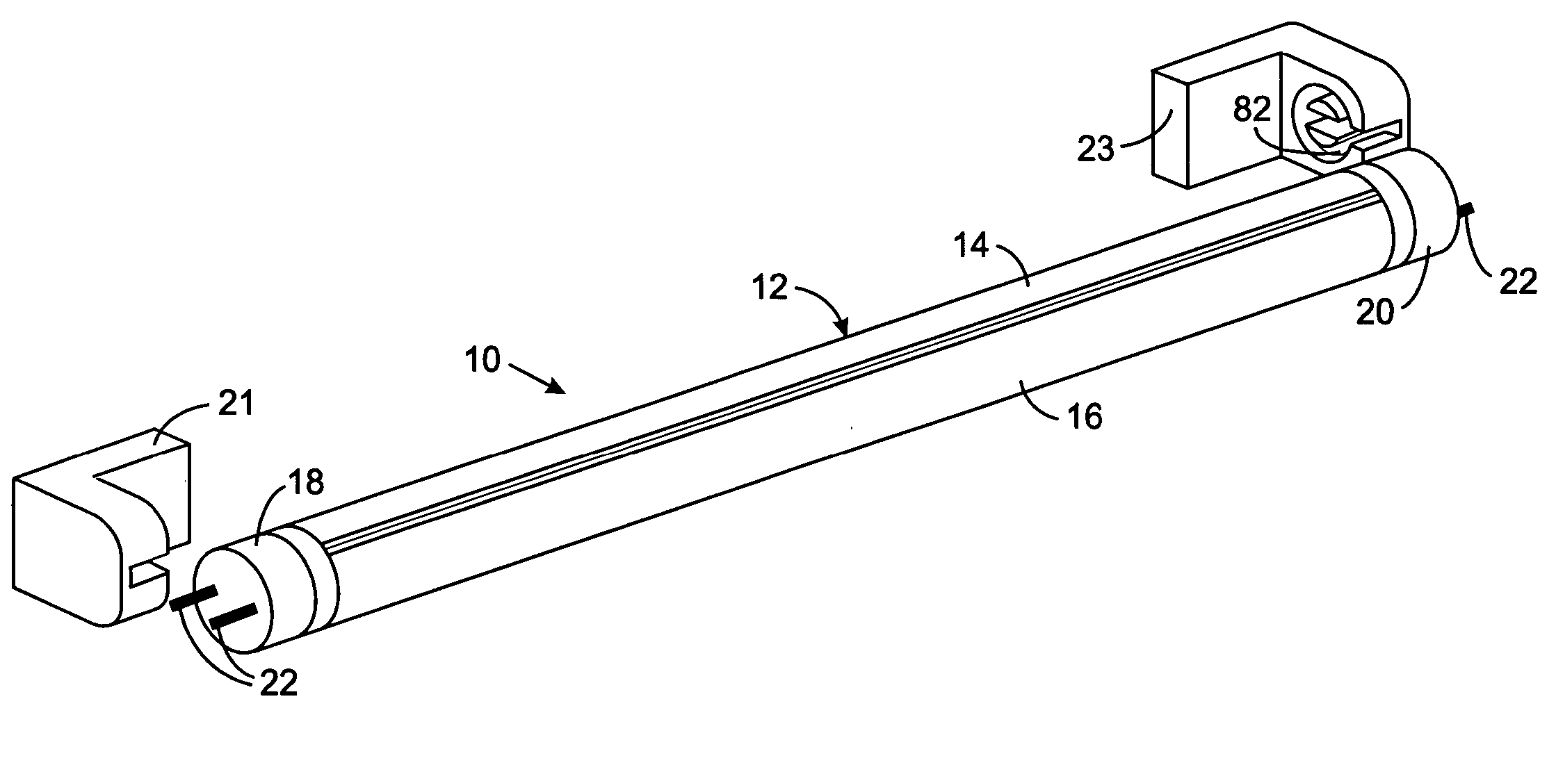
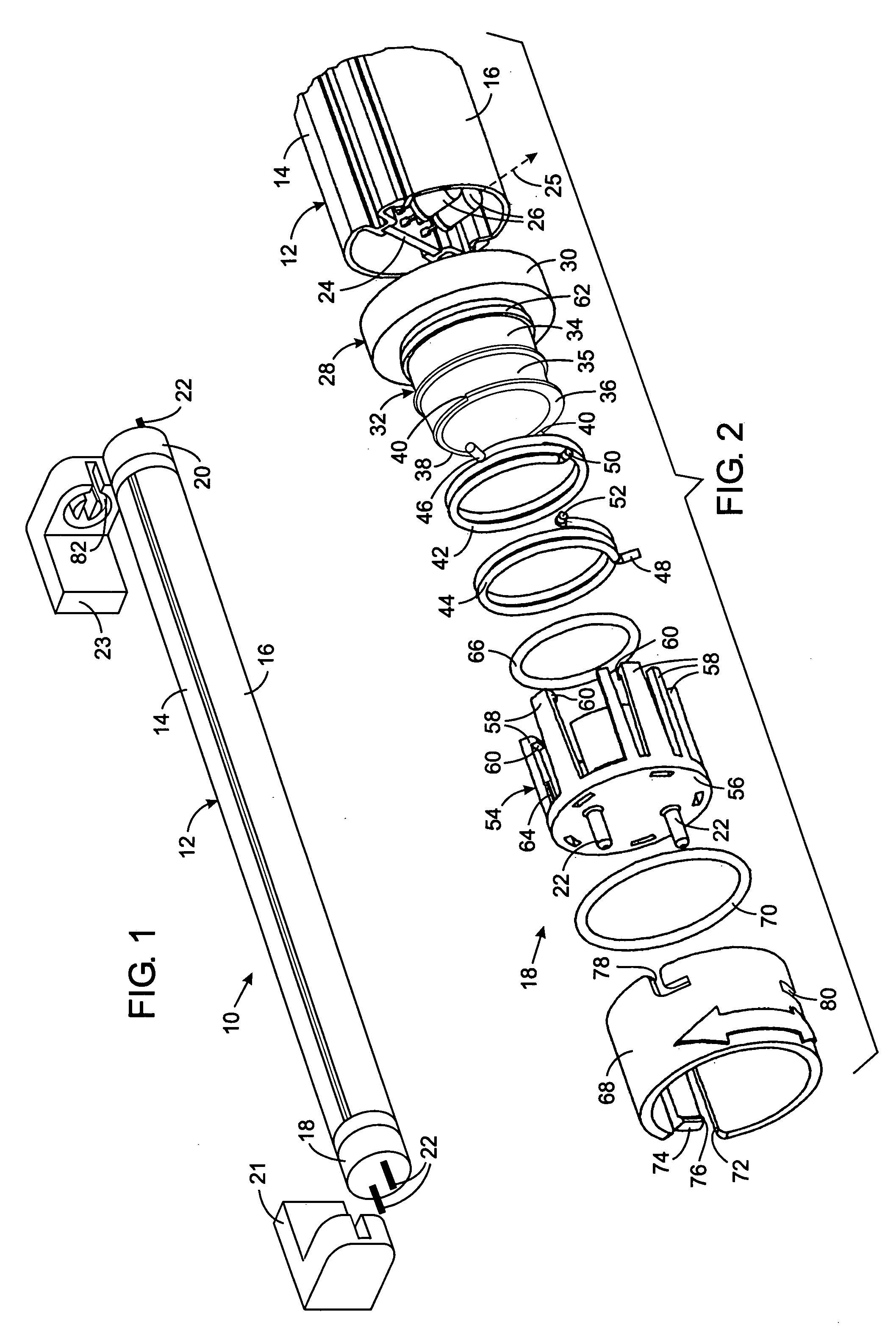
[0023] With initial reference to FIG. 1, a first lighting assembly 10 includes an elongated, tubular housing 12 comprising a rigid curved back portion 14 and a curved transparent front portion 16. A pair of connectors 18 and 20 are located at opposite ends of the housing 12 and have pin-type electrical terminals 22 that serve as terminals for making electrical contact with a pair of standard fluorescent tube sockets 21 and 23 between which the first lighting assembly 10 fits. In some versions of the first lighting assembly 10, electricity is supplied through only one end of the housing, in which case the electrical terminals 22 on the connector at the opposite end engage a socket merely to support that end of the housing. The standard fluorescent tube sockets 21 and 23 form a light fixture.

[0024] With reference to FIG. 2, the housing 12 contains a circuit board 24 having a plurality of high intensity light emitting diodes (LED's) 26 mounted on one side facing the transparent front ...


PUM


Abstract

A lighting assembly has an elongated housing which contains a plurality of light emitting diodes that send light from one side of the housing. Connectors at the ends of the housing are provided to connect the lighting assembly into standard sockets of a fluorescent light fixture that has been modified to power the light emitting diodes. At least one of the connectors has a releasable holding mechanism that allows the housing to be rotated with respect to the sockets to aim the light is a desired direction and then hold the housing in that orientation.

Description

CROSS-REFERENCE TO RELATED APPLICATIONS [0001] Not Applicable STATEMENT REGARDING FEDERALLY SPONSORED RESEARCH OR DEVELOPMENT [0002] Not Applicable BACKGROUND OF THE INVENTION [0003] 1. Field of the Invention [0004] The present invention relates to light emitting diode assemblies that are useful to illuminate the interior of a vehicle, such as an aircraft, and more particularly to tubular assemblies having a housing that contains a plurality of light emitting diodes. [0005] 2. Description of the Related Art [0006] Aircraft cabins have been illuminated by fluorescent lighting systems. The disadvantages of that type of lighting include the relatively short life of the fluorescent lamp, significant weight of the ballast, heat production, generation of radio frequency interference (RFI), and fragility. [0007] One solution to counter the problems identified above has been to use an assembly of light emitting diodes (LED). U.S. Pat. No. 6,158,882 describes an aircraft lighting system whic...

Claims


Application Information

Patent Timeline
Patent Type & Authority Applications(United States)
IPC IPC(8): F21V21/00F21K99/00
CPCF21K9/17F21K9/175F21K9/58F21V21/30F21Y2101/02F21Y2103/00F21Y2103/003F21V14/02F21K9/65F21Y2103/10F21Y2115/10F21K9/272F21K9/27
Inventor LEFEBVRE, PHILLIP E.DRISCOLL, DAVID DELORY JR.
Owner BE AEROSPACE INCORPORATED
Why Eureka
Try Eureka