Golf club shaft

a golf club and shaft technology, applied in the direction of golf clubs, golf courses, sport apparatus, etc., can solve the problems of low torsional rigidity of carbon shafts, low strength, and inability to hit balls in the direction of balls, and achieve the effect of good feeling when the player swings and a proper degree of flexibility

Inactive Publication Date: 2006-06-15
DUNLOP SPORTS CO LTD
View PDF5 Cites 19 Cited by
  • Summary
  • Abstract
  • Description
  • Claims
  • Application Information

AI Technical Summary

Benefits of technology

[0046] As apparent from the foregoing description, according to the present invention, the formation of the rib allows the shaft composed of the metal tube to have a necessary rigidity and strength. Thereby it is possible to thin the base of the shaft. Therefore the metal shaft of the present invention is more lightweight than the conventional m

Problems solved by technology

The carbon shaft has a low torsional rigidity and is unstable in the direction of a hit ball.
However, to manufacture a shaft that allows female and senior players to swing easily, these conventional arts are required to reduce the weight of the shaft by th

Method used


Image

  • Golf club shaft
  • Golf club shaft
  • Golf club shaft

Examples


example 1

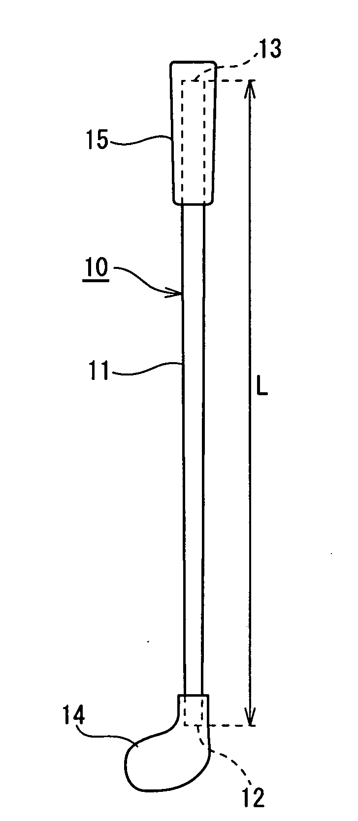
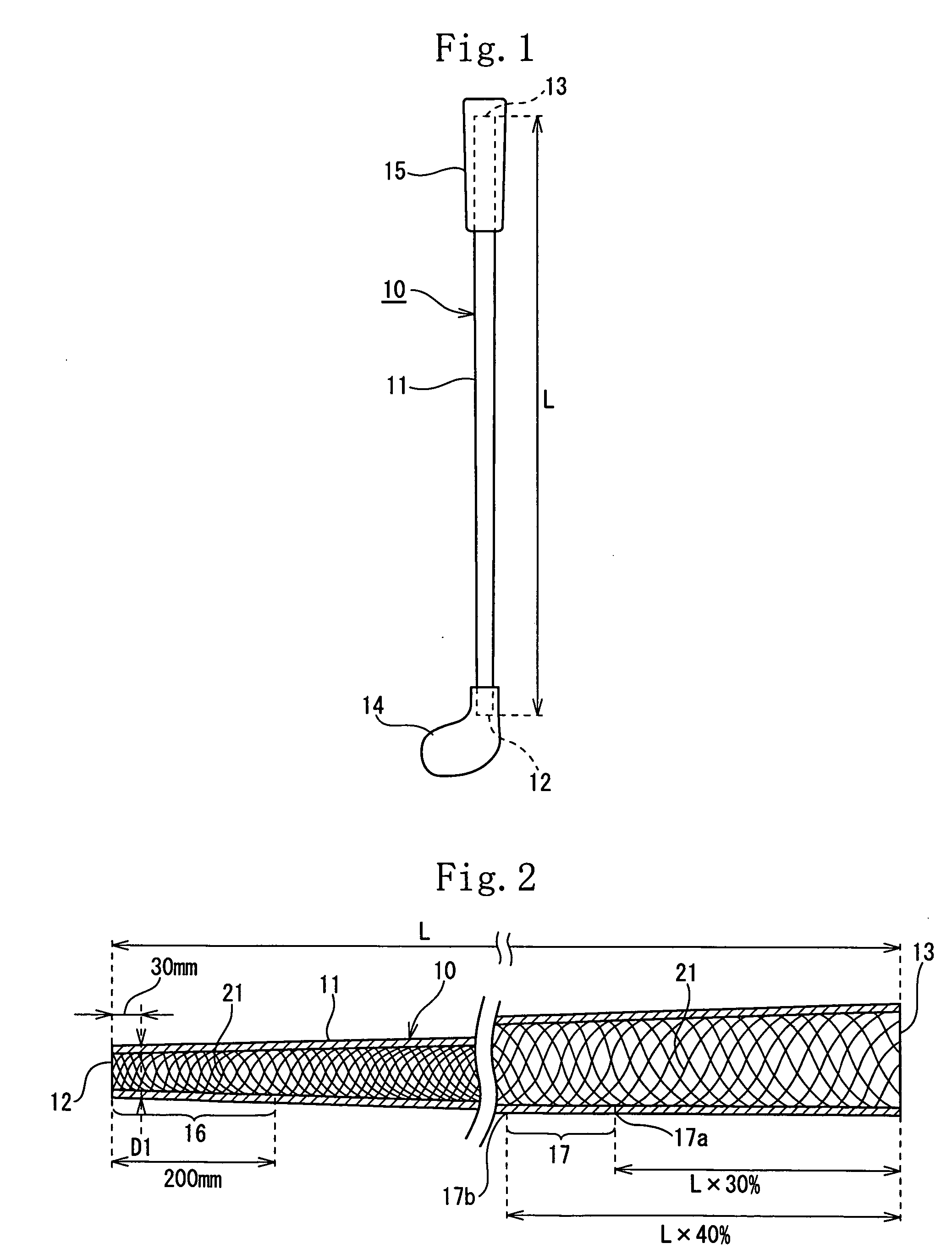
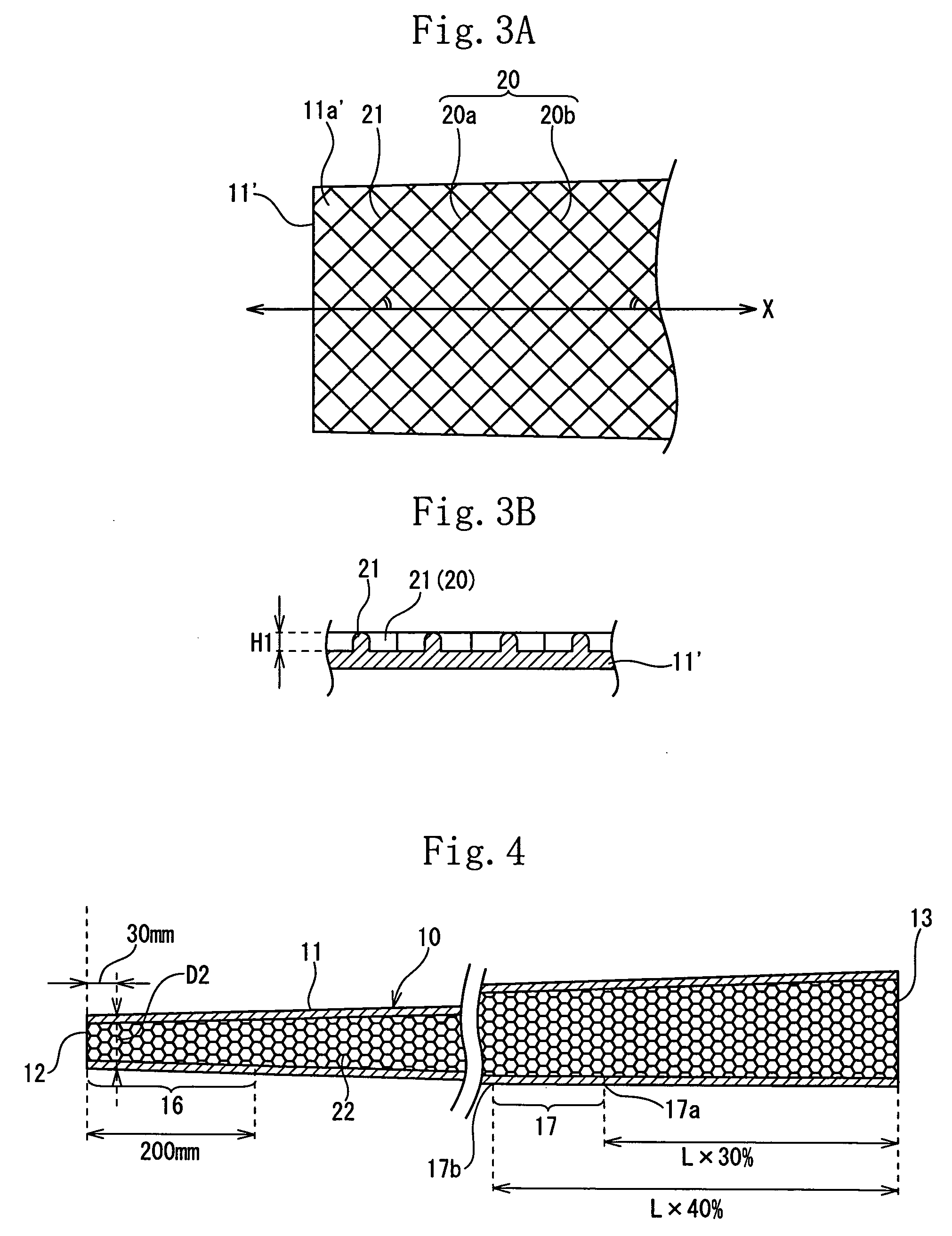
[0101] The shaft of the example 1 had the same construction as that of the shaft of the first embodiment. More specifically, the weight of the shaft was set to 65 g. The outer diameter of the shaft at the position spaced at 30 mm from the head-side front end 12 was set to 9.5 mm. The internal rib 21 was composed of the spiral rib 20a and the spiral rib 20b intersected with the spiral rib 20a. The internal rib 21 was formed over the full length of the shaft 10. The internal rib 21 was projected at a height H1 of 0.3 mm from the inner peripheral surface of the shaft 10. The rigidity value (EI value) of the shaft 10 at the position spaced at 90 mm from the head-side front end 12 was set to 1.4 kg·mm2. The rigidity value of the grip-side reinforcing region 17 was set to 4.2 kg·mm2.

example 2

[0102] The shaft of the example 2 had the same construction as that of the shaft of the second embodiment. More specifically, the weight of the shaft was set to 55 g. The outer diameter of the shaft at the position spaced at 30 mm from the head-side front end 12 was set to 10.1 mm. The internal rib 22 was honeycomb. The internal rib 22 was formed over the full length of the shaft 10. The internal rib 22 was projected at a height H1 of 0.3 mm from the surface of the shaft 10. The rigidity value (EI value) of the shaft 10 at the position spaced at 90 mm from the head-side front end 12 was set to 1.5 kg·mm2. The rigidity value of the grip-side reinforcing region 17 was set to 4.5 kg·mm2.

example 3

[0103] The shaft of the example 3 had the same construction as that of the shaft of the third embodiment. More specifically, the weight of the shaft was set to 65 g. The outer diameter of the shaft at the position spaced at 30 mm from the head-side front end 12 was set to 9.5 mm. The internal rib 23 was composed of the spiral rib 23A which is formed at head side of the shaft 10 and the spiral rib 23B which is formed at grip side thereof. The internal ribs 23 were formed in the region ranging from the head-side front end 12 to the position spaced at 180 mm from the head-side front end 12 and in the region ranging from the grip-side rear end 13 to the position spaced at 200 mm from the grip-side rear end 13. The internal rib 23 was projected at a height H1 of 0.5 mm from the inner peripheral surface of the shaft 10. The rigidity value (EI value) of the shaft 10 at the position spaced at 90 mm from the head-side front end 12 was set to 1.4 kg·mm2. The rigidity value of the grip-side re...


PUM


Abstract

A golf club shaft (10) composed of a metal tube and having a weight not less than 50 g and less than 85 g. A rib (21) is formed on an inner peripheral surface of the golf club shaft (10) and/or a peripheral surface thereof. A rigidity value (EI value) of the golf club shaft (10) at a position spaced at 90 mm from a head-side front end (12) thereof is set to not less than 1.0 kg·mm2 nor more than 2.5 kg·mm2. An outer diameter (D1) of the golf club shaft (10) at a position spaced at 30 mm from the head-side front end (12) thereof is set to not less than 9.5 mm nor more than 15.0 mm.

Description

[0001] This Nonprovisional application claims priority under 35 U.S.C. § 119(a) on Patent Application No(s). 2004-357416 filed in Japan on Dec. 9, 2004, the entire contents of which are hereby incorporated by reference. FIELD OF THE INVENTION [0002] The present invention relates to a golf club shaft and particularly a golf club shaft, composed of a metal tube, which is lightweight and has a high strength. DESCRIPTION OF THE RELATED ART [0003] In recent years, to increase the speed of a hit golf ball and hit the golf ball stably, there is a tendency for golf club shaft manufacturers to manufacture a lightweight golf club shaft by making the head heavy concentratedly. Therefore a carbon shaft composed of fiber reinforced resin such as carbon prepreg which is lightweight and has a high specific strength and specific rigidity is most widely used. [0004] The carbon shaft has a low torsional rigidity and is unstable in the direction of a hit ball. Thus in recent years, high-class players ...

Claims


Application Information

Patent Timeline
IPC IPC(8): A63B53/12A63B102/32
CPCA63B53/12A63B59/0014A63B60/10A63B60/06A63B60/08A63B60/00
Inventor KUMAMOTO, TOMIO
Owner DUNLOP SPORTS CO LTD
Why Eureka
Try Eureka