
Polyaxial screw

a polyaxial screw and screw technology, applied in the field of orthopedic fixation devices, can solve the problems of limiting the range of motion, injuring the nervous system within the spinal column, and unable to perform surgery,

Active Publication Date: 2006-06-15
GLOBUS MEDICAL INC
View PDF39 Cites 371 Cited by
  • Summary
  • Abstract
  • Description
  • Claims
  • Application Information

AI Technical Summary

Benefits of technology

[0011] In one embodiment, the cap is capable of rotating to first and second positions relative to the skirt. Rotation of the cap relative to the skirt may cause the cap to press the elongate rod toward the coupling ring so that the coupling ring arms apply pressure against the plurality of stops and lock the skirt in position relative to the bone fastener.

Problems solved by technology

Many types of spinal irregularities can cause pain, limit range of motion, or injure the nervous system within the spinal column.
These irregularities can result from, without limitation, trauma, tumor, disc degeneration, and disease.
It is well known that difficulties can arise during a surgical procedure when attempting to connect a vertical solid member, such as a rod, to a bone screw.
While these designs may provide an advantage of reducing assembly time over earlier screw designs by requiring clamping of only one fastener to hold the rod and coupling element by applying pressure against the head of the bone screw, such systems lack the ability to separately unlock or release one element, such as the rod or the coupling element.

Method used


Image

  • Polyaxial screw
  • Polyaxial screw
  • Polyaxial screw

Examples


Embodiment Construction

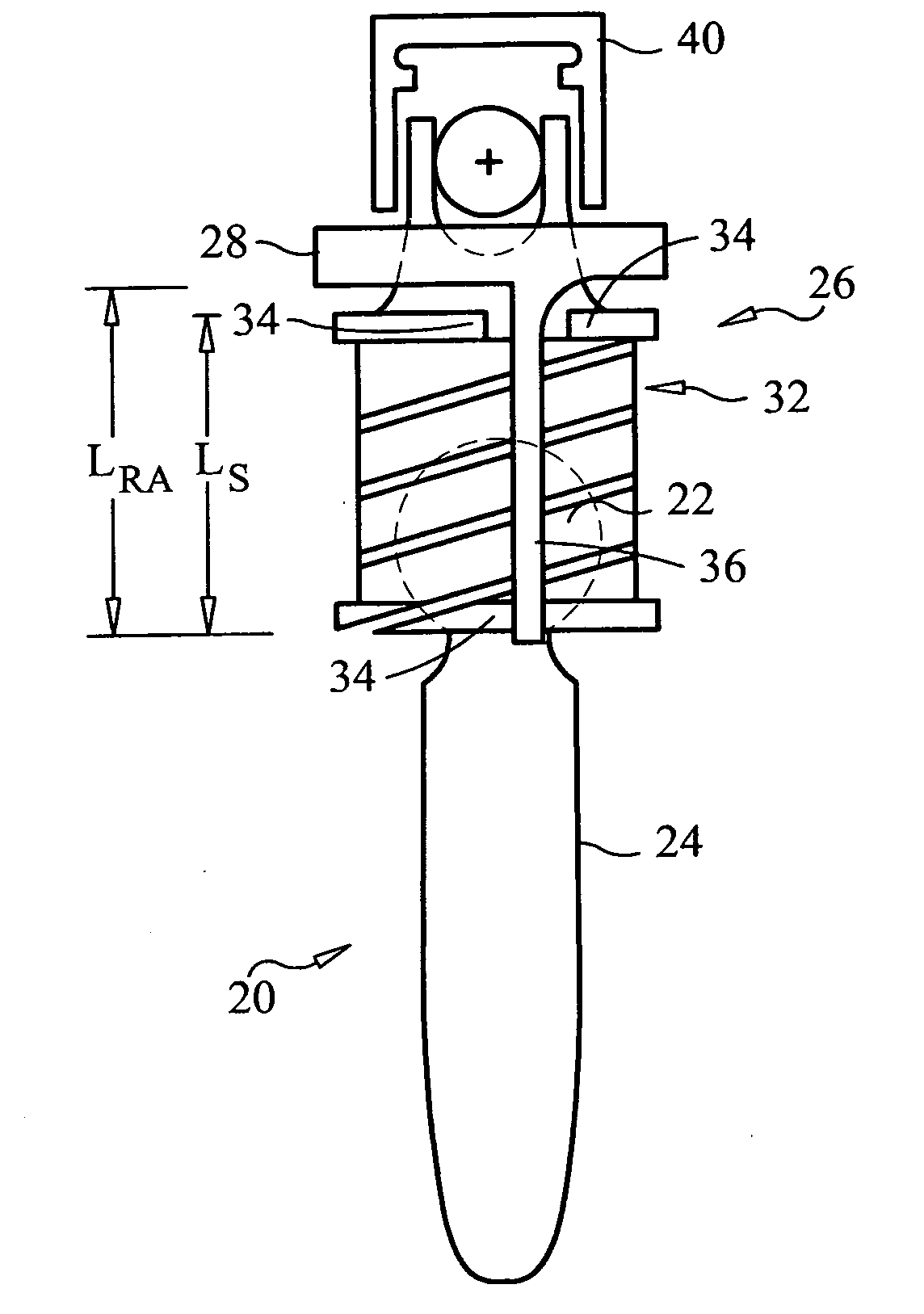
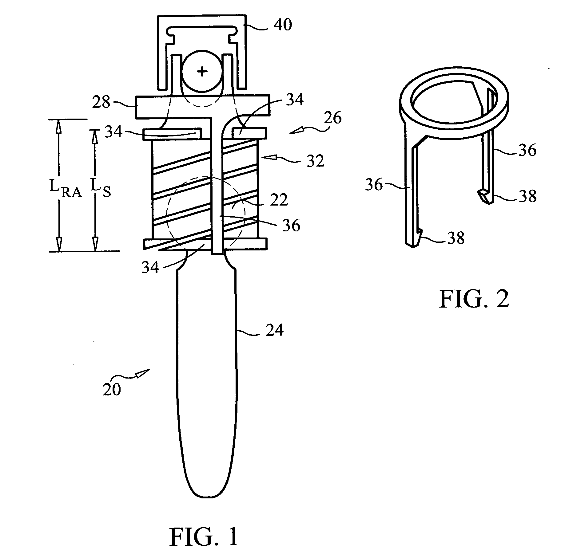
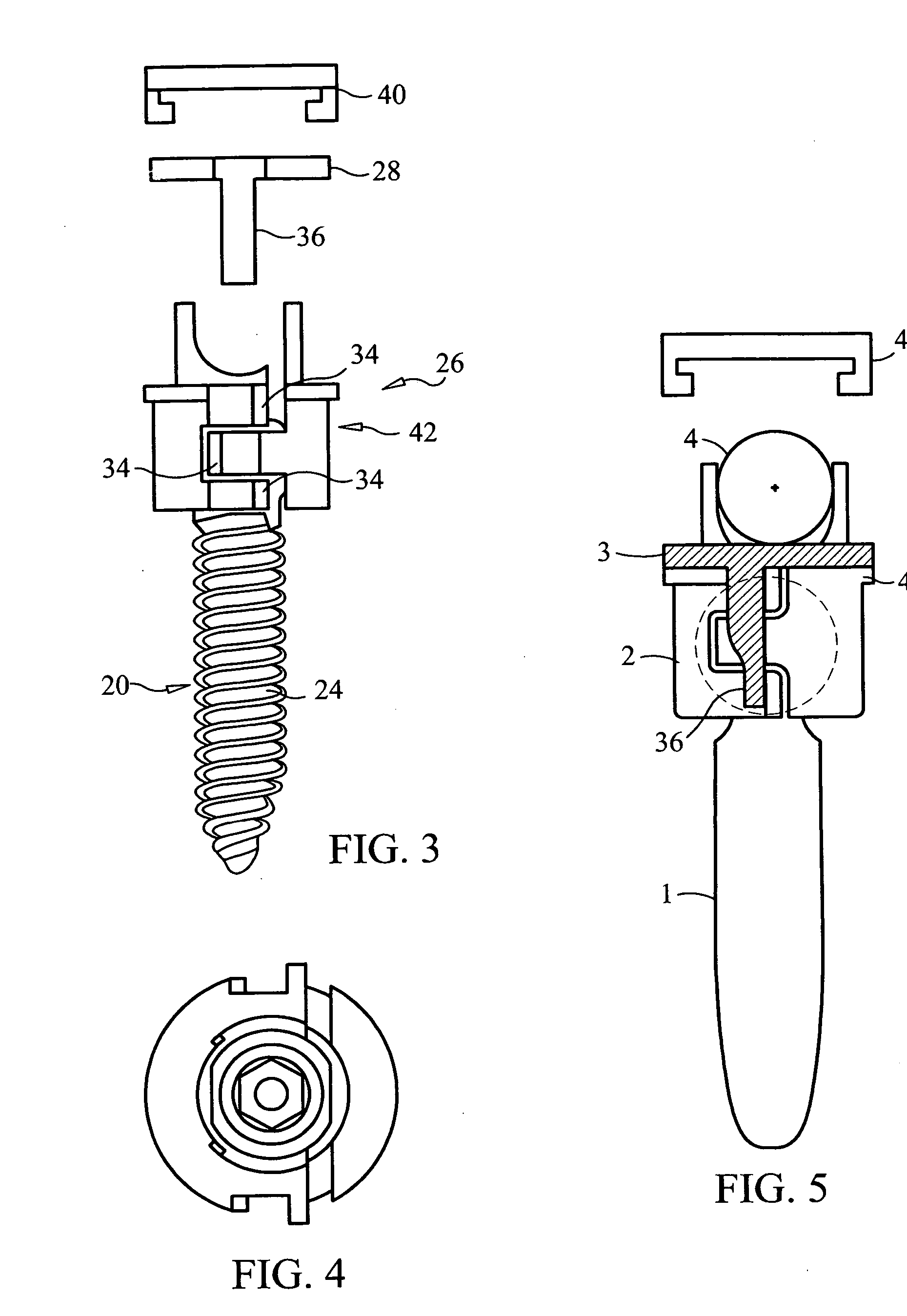
[0087] The present invention generally is directed toward a spinal fixation system whereby the locking of an elongate rod plays may not be necessary in order to lock the angle between a fastener, such as a screw, and a coupling element. Instead of requiring full application of locking pressure on an elongated rod in order to lock the coupling element securely in place with respect to the screw head, some embodiments of the present invention utilize a coupling locking device that is capable of securing the coupling element to the screw independent of the rod or with forces imparted by the rod that are less than the forces used to lock the rod in place. Likewise, some embodiments of the present invention also may utilize a rod locking device that is capable of securing the rod to the coupling element in a manner that is independent of the coupling locking device. In addition, some embodiments of the present invention permit a coupling element to lock in place relative to the fastener ...


PUM


Abstract

The present invention generally is directed toward a spinal fixation system whereby a coupling element allows the physician to selectively lock or unlock either the connection between the coupling element and a fastener, such as to allow for repositioning of the coupling element, or the connection between the coupling element and an elongate rod. The locking or unlocking of these connections may be made independently and as desired by the physician.

Description

CROSS-REFERENCE TO RELATED APPLICATIONS [0001] The application claims priority to U.S. application Ser. No. 10 / 819,994 filed on Apr. 8, 2004 and U.S. application Ser. No. 11 / 146,147 filed on Jun. 7, 2005 both of which are incorporated herein in their entireties by reference theretoFIELD OF THE INVENTION [0002] The present invention relates to orthopedic fixation devices comprising a rod and a bone screw having a variable angle head. The variable angle head of the bone screw has a coupling element that can independently lock the angulation of the head relative to the screw axis and securely prevent movement of the rod within the variable angle head. BACKGROUND OF THE INVENTION [0003] Many types of spinal irregularities can cause pain, limit range of motion, or injure the nervous system within the spinal column. These irregularities can result from, without limitation, trauma, tumor, disc degeneration, and disease. Often, these irregularities are treated by immobilizing a portion of t...

Claims


Application Information

Patent Timeline
Patent Type & Authority Applications(United States)
IPC IPC(8): A61F2/30
CPCA61B17/7032A61B17/7035A61B17/7002A61B17/70A61B17/7037
Inventor IOTT, ANDREWLEE, ANDREWBINDER, LARRYPAUL, DAVID C.
Owner GLOBUS MEDICAL INC
Learn More