On-demand printing of coding patterns

a technology of coding pattern and printing, applied in the field of printing of coding pattern, can solve the problems of excessive transfer time and printer processing time of such cod

Inactive Publication Date: 2006-06-22
ANOTO AB
View PDF11 Cites 12 Cited by
  • Summary
  • Abstract
  • Description
  • Claims
  • Application Information

AI Technical Summary

Problems solved by technology

Consequently, transfer times and printer processing times for such code may become excessive.

Method used


Image

  • On-demand printing of coding patterns
  • On-demand printing of coding patterns
  • On-demand printing of coding patterns

Examples


Embodiment Construction

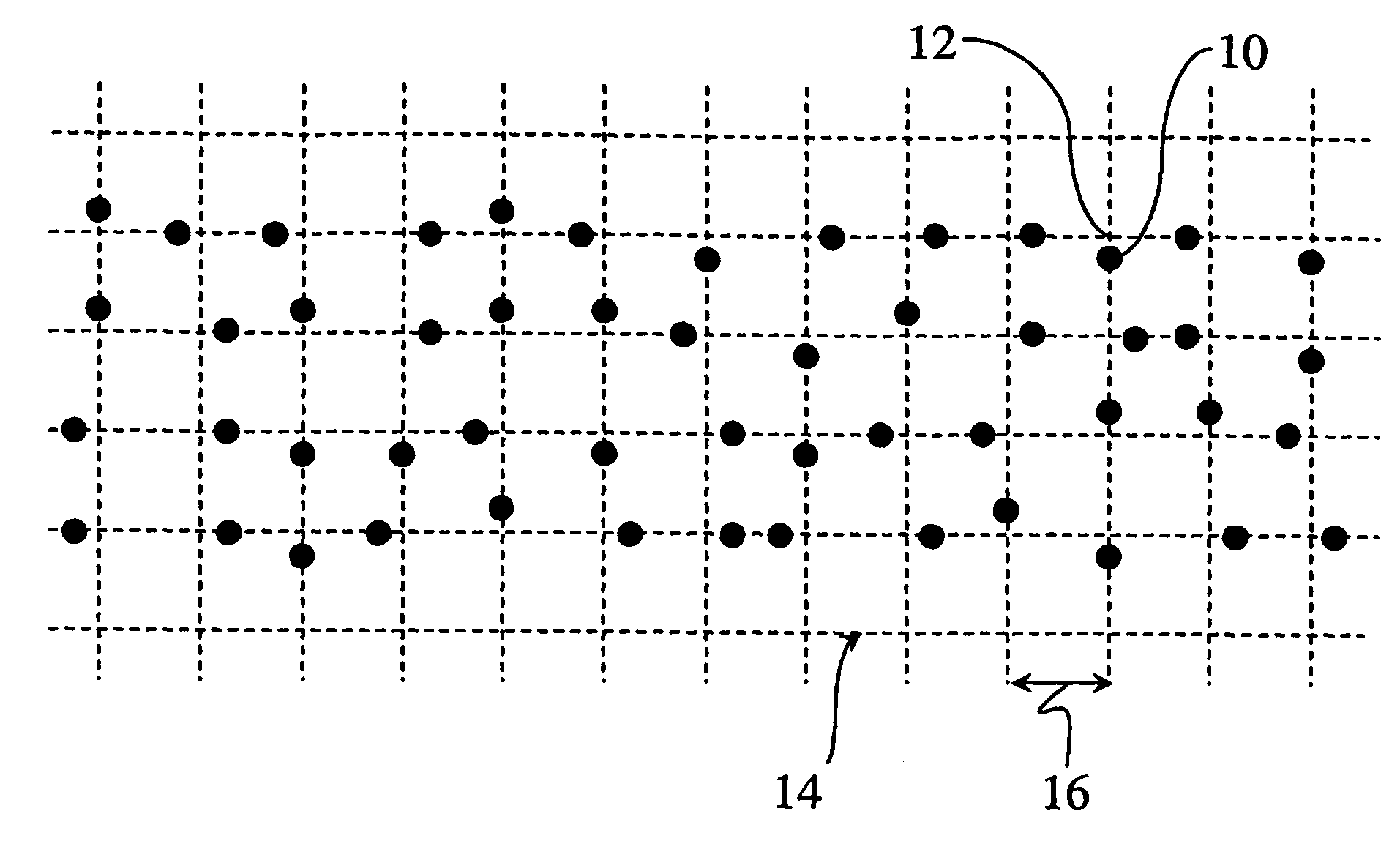
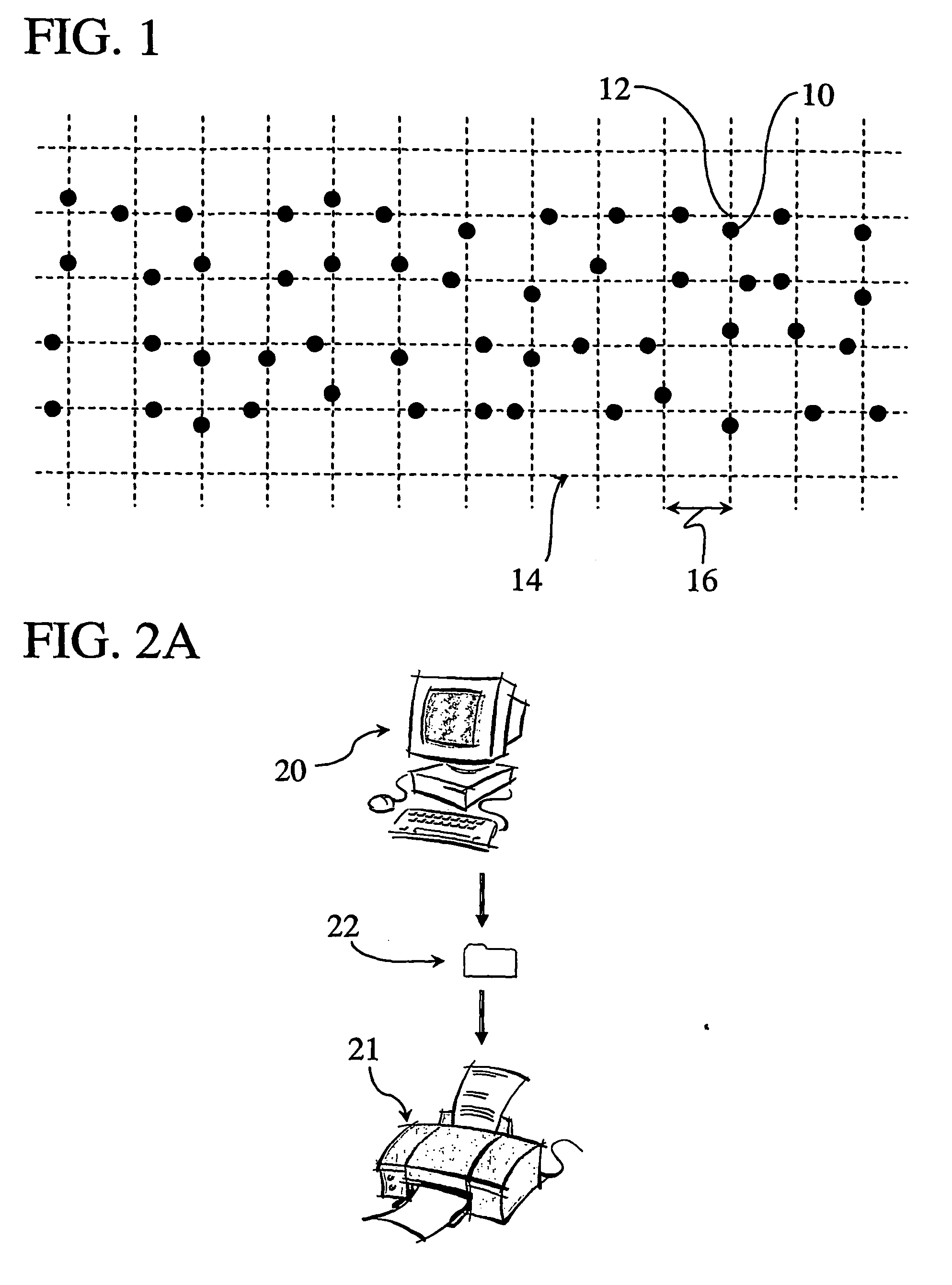
[0026]FIG. 1 illustrates a part of an absolute position-coding pattern, which will be used to exemplify the invention. The position-coding pattern is detailed in Applicant's International Patent Publications WO 01 / 26032 and WO 03 / 001440, which are incorporated herein by this reference. Principally, the coding pattern of FIG. 1 is made up of simple graphical symbols, which can assume four different values and thus are capable of coding two bits of information. Each symbol consists of a mark 10 and a spatial reference point or nominal position 12, the mark 10 being displaced or offset a distance in one of four different directions from the nominal position 12. The value of each symbol is given by the direction of displacement. The symbols are arranged with the nominal positions 12 forming a regular raster or grid 14 which may be virtual and thus not explicitly included in the coding pattern.

[0027] In the following, it is assumed that coding pattern of FIG. 1 is used to code absolute ...


PUM


Abstract

A computer-implemented method is designed for on-demand printing on digital printers of a coding pattern to code data on a surface. The coding pattern comprises a plurality of parallel number sequences which represent different rotations of a cyclic number sequence. The method could involve retrieving a digital representation of the coding pattern, and identifying the rotations therein to derive shift information which designates a phase difference between each rotation and the cyclic number sequence. In the printing operation, all the different rotations may be represented by the cyclic number sequence embodied as at least one code block image. This code block image is repeated in accordance with the shift information to form a printable image in the printer.

Description

CROSS-REFERENCE TO RELATED APPLICATIONS [0001] The present application claims the benefit of Swedish patent application No. 0301729-0, filed on Jun. 13, 2003, and U.S. Provisional patent application No. 60 / 477,926, filed on, Jun. 13, 2003, which both are hereby incorporated by reference.FIELD OF THE INVENTION [0002] The present invention generally relates to printing of coding patterns on on-demand digital printers. BACKGROUND ART [0003] It is known to use a coding pattern to embed some type of information in a passive base such as a sheet of paper, a writing board or equivalent. A suitably programmed scanner, fax machine, camera or digital pen can then read, recreate and use the information embedded locally in the base. For example, graphical information on a base can be supplemented with embedded information which extends the functionality of the base. Such embedded information can comprise file data for full or partial recreation of the graphical information, commands, supplement...

Claims


Application Information

Patent Timeline
Patent Type & Authority Applications(United States)
IPC IPC(8): B41J5/30G06F3/03G06K11/06G06K15/02G06K19/06
CPCG06K15/02G06K19/06009G06K2215/0082H04N1/32144H04N1/32203H04N1/32219H04N1/32229G06K15/1852G06K11/06
Inventor LYNGGAARD, STEFAN
Owner ANOTO AB
Why Eureka
Try Eureka