Handle/grip and method for designing the like

a design method and technology of a handle, applied in the direction of steering devices, mechanical control devices, instruments, etc., can solve the problems of different flexor muscles pulling different parts of the fingers, kinks of nerves and tendons, and inability to work in concert with the flexor muscles to grip a common handle, etc., to achieve the effect of efficient use of the hand

Inactive Publication Date: 2006-06-29
TILLIM STEPHEN L +1
View PDF99 Cites 25 Cited by
  • Summary
  • Abstract
  • Description
  • Claims
  • Application Information

AI Technical Summary

Benefits of technology

[0028] An advantage of a handle of this design is that it does not contact the skin over the TCL because of the recessed proximal part of the middle section. Therefore the TCL is not compressed and no pressure is transmitted to the contents of the CT region during gripping or using a handle of this design as a support.
[0058] According to another specific aspect of the present invention, the periphery of the handle can be combined into a glove to provide versatility in use of the handle for various applications.

Problems solved by technology

A problem can result in that the extremes of wrist movement can kink the nerve and tendons where they enter the CT 203.
Therefore, a problem can develop in that the different flexor muscles pulling different parts of the fingers 606-609 to grip a common handle do not work in concert.
Such asymmetric use of forearm finger flexor muscles is forced by use of common handles and grips for tools and implements as for heavy equipment, machines, appliances and other devices and can frequently cause problems.
The device merely adds firmness to the web space, where the long fingers lie across a handle as shown on a baseball bat, but the median nerve pressure problem remains.

Method used


Image

  • Handle/grip and method for designing the like
  • Handle/grip and method for designing the like
  • Handle/grip and method for designing the like

Examples


Embodiment Construction

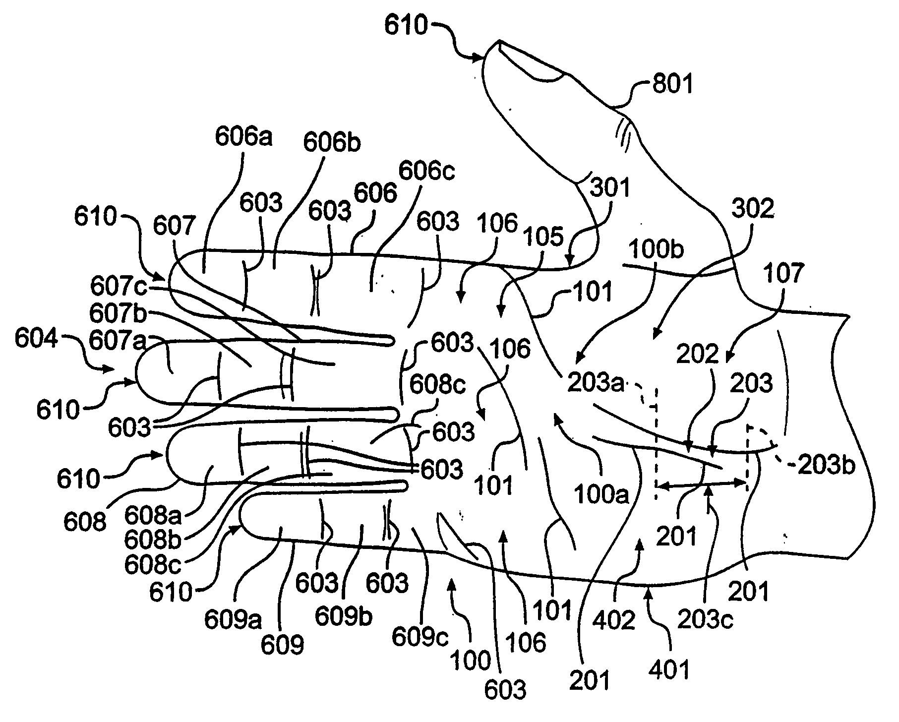
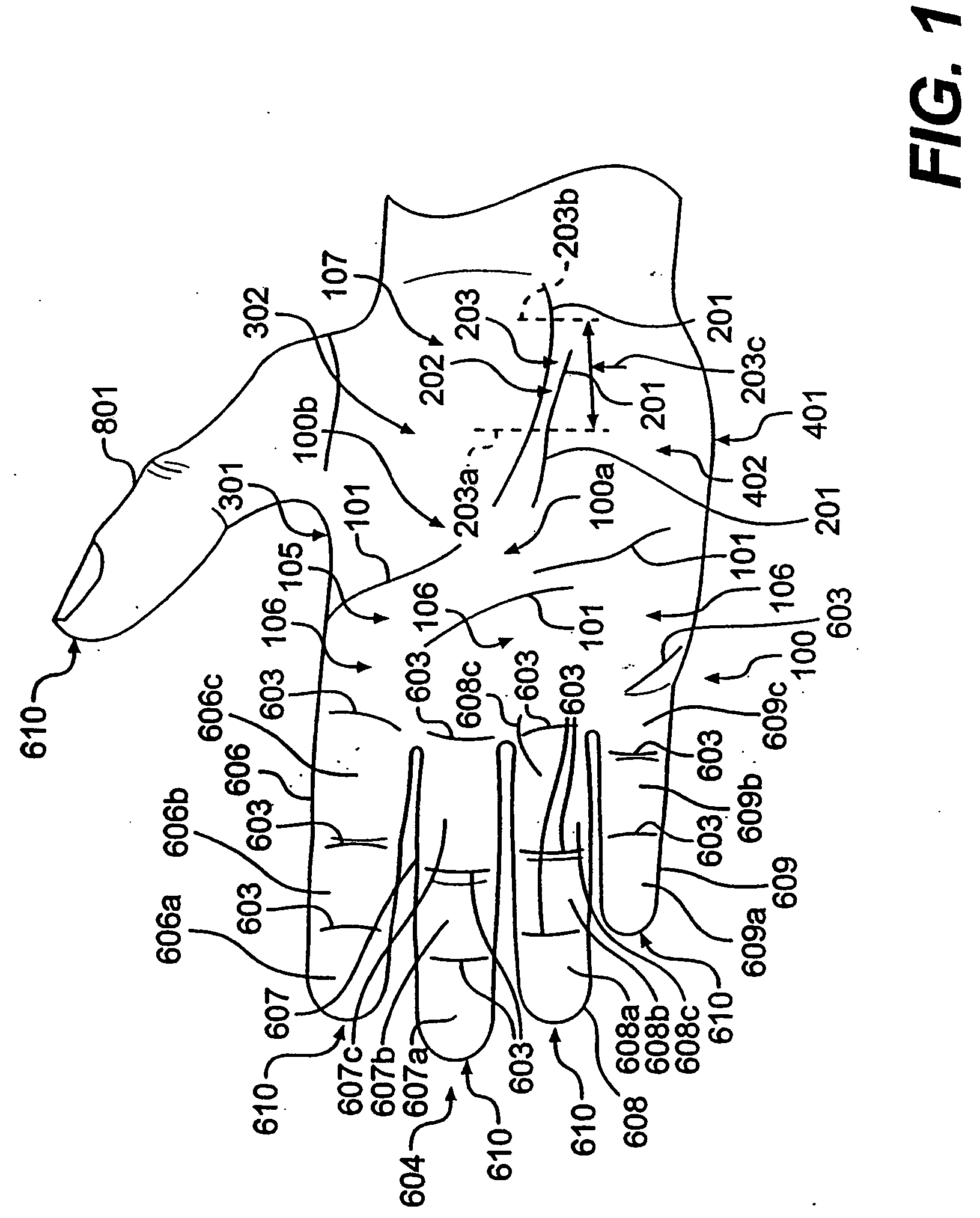
[0102] In order to more clearly and concisely describe the subject matter of the present invention, the following definitions are intended to provide guidance as to the meanings of specific terms used in the following written description. Also it is to be understood that the phraseology or terminology employed herein is for the purpose of description and not to be construed as limiting. The following sections relate to areas of the hand described in the background information and refer to FIG. 1.

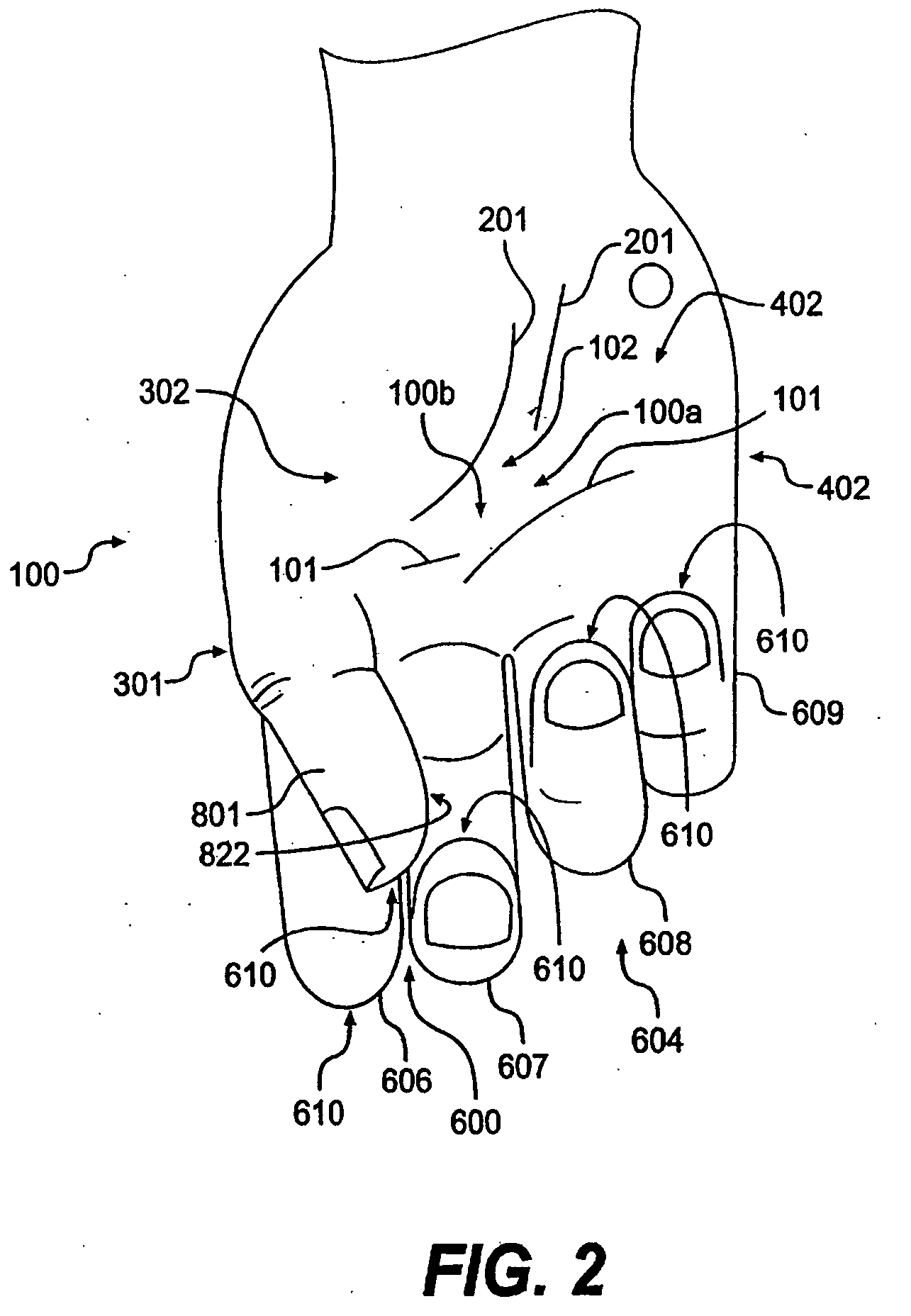
Neutral Hand Position—‘N Position’

[0103]FIG. 2 shows a right hand in the neutral position. This position is the anatomic position at rest. It is called the neutral hand or ‘N Position’. This universal human hand pattern is related to the shoulder and elbow resting positions and the way the carpal, metacarpal and phalangeal bones angle with each other when the upper extremity is dangling vertically at rest. The hand 100 is illustrated in FIG. 2 from the perspective of the palm 100b as if it...


PUM


Abstract

An apparatus for use with a hand includes a handle body with an ulnar section for engaging the palmar arch of the hand, the ulnar section having a distal ulnar side for receiving the small finger of the hand and having a palmar ulnar side, the palmar ulnar side having a surface for engaging a portion of the palmar surface of the hand so as to position the end of the small finger in substantial alignment with the ends of the middle finger and the ring finger and to position the handle within the hand without engaging a surface of the hand located over the carpal tunnel; and a compressible and resilient proximal-side surface supported by a supporting mechanism so as to maintain a proximal-side desirable shape different from a shape of the proximal side of the handle body.

Description

CLAIM FOR PRIORITY [0001] This application is a Continuation-In-Part application of U.S. application Ser. No. 11 / 203,303 filed on Aug. 15, 2005, the entire disclosure of which is incorporated herein by reference, which claims the priority of U.S. application Ser. No. 10 / 279,111 filed on Oct. 24, 2002 and issued into U.S. Pat. No. 6,988,295 on Jan. 24, 2006, and U.S. Provisional Patent Application Ser. No. 60 / 330,527 filed on Oct. 24, 2001, the entire disclosure of which is incorporated herein by reference.FIELD OF THE INVENTION [0002] The present invention provides a design method and apparatus for a handle or grip providing a shape and structure that fills various regions inside the hand except a region at an area of the hand over the underlying carpal tunnel. Such design method and apparatus provides for various supports and handles for use by a hand. In particular, the apparatus for use with a hand includes a handle body with an ulnar section for engaging the palmar arch of the h...

Claims


Application Information

Patent Timeline
Patent Type & Authority Applications(United States)
IPC IPC(8): B25G1/10
CPCA63B49/08A63B59/0025A63B59/0029A63C11/222Y10T16/476B43K23/008B62K21/26G05G1/06B25G1/102A63B60/12A63B60/10A63B60/08A63B60/14A45C13/26
Inventor TILLIM, STEPHEN L.FISHER, STANLEY P.
Owner TILLIM STEPHEN L
Why Eureka
Try Eureka