Anvick aperture device and method of forming and using same

a technology of aperture device and aperture, which is applied in the direction of building components, structural elements, towers, etc., can solve the problems of increased raw material cost, unfamiliar and unembraced, and increased land and labor costs

Inactive Publication Date: 2006-06-29
ANVICK THEODORE E +1
View PDF35 Cites 25 Cited by
  • Summary
  • Abstract
  • Description
  • Claims
  • Application Information

AI Technical Summary

Problems solved by technology

However, they have been unfamiliar to and have not been embraced by a construction industry well versed in prevalent wood, concrete masonry and steel building methods.
Adoption of more stringent mandatory building code requirements with respect to seismic, wind, and fire resistance and energy conservation has progressed over the years, land and labor costs have risen, and the cost of raw materials has increased.
This has caused the costs of the development of wood, steel frame, masonry block and poured in place concrete structures to rise significantly.
Rising maintenance, and energy costs for finished structures have also increased the costs of operation and ownership.
The

Method used


Image

  • Anvick aperture device and method of forming and using same
  • Anvick aperture device and method of forming and using same
  • Anvick aperture device and method of forming and using same

Examples


Embodiment Construction

—DESCRIPTION

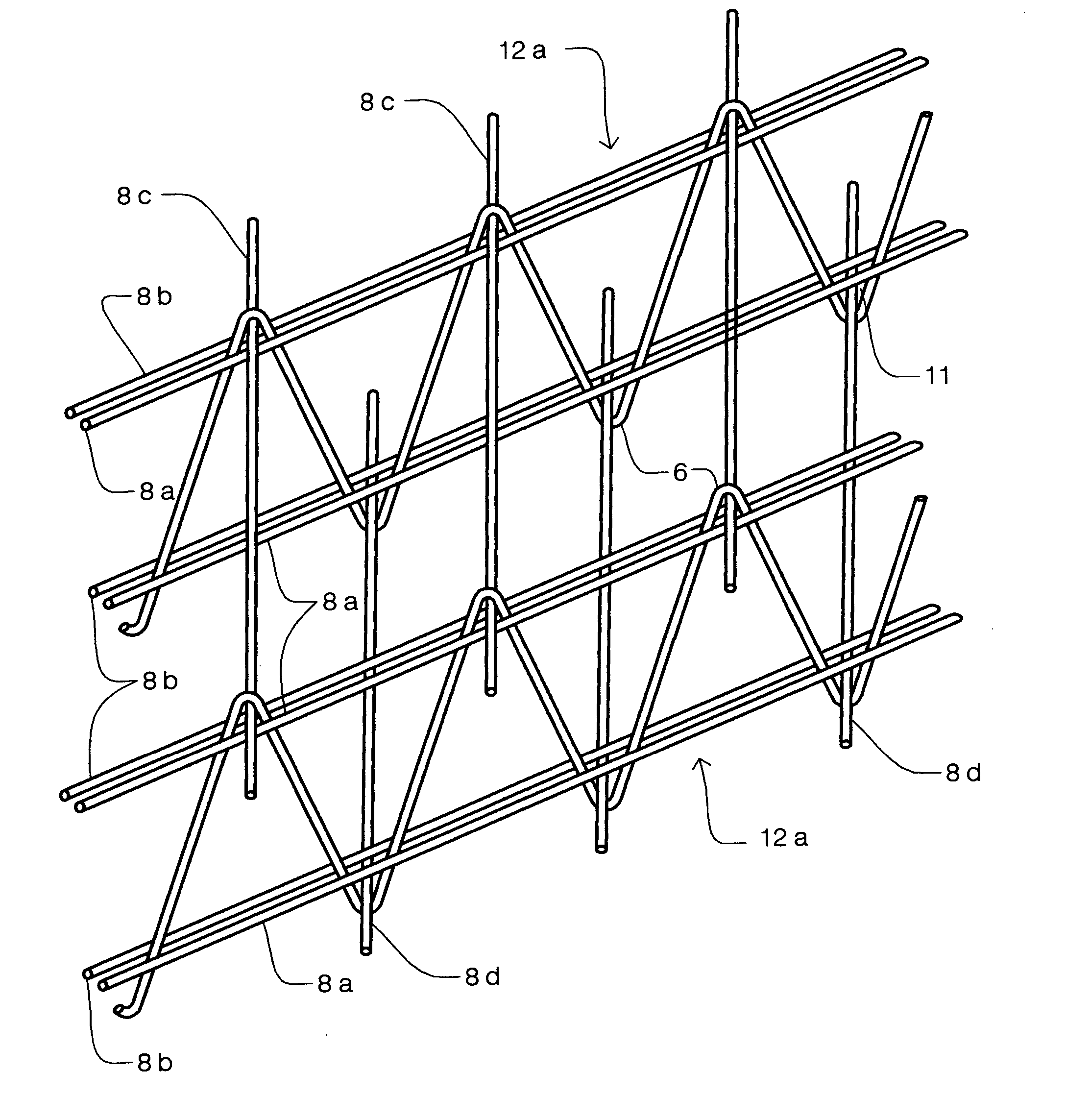
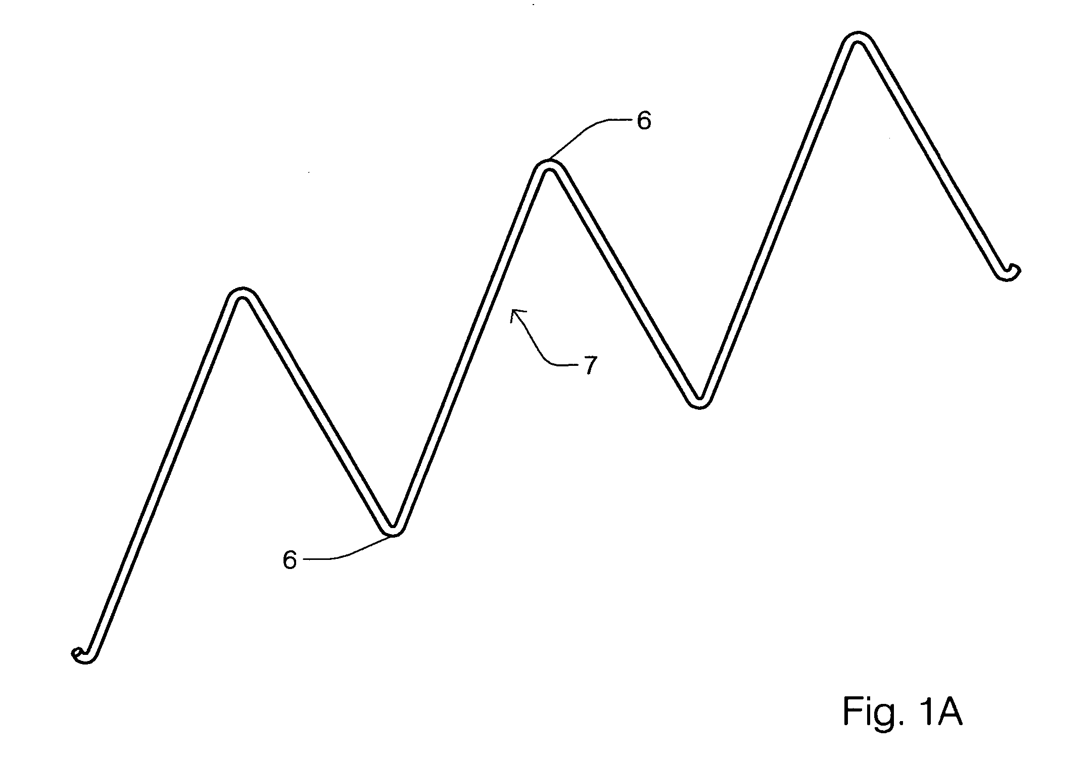
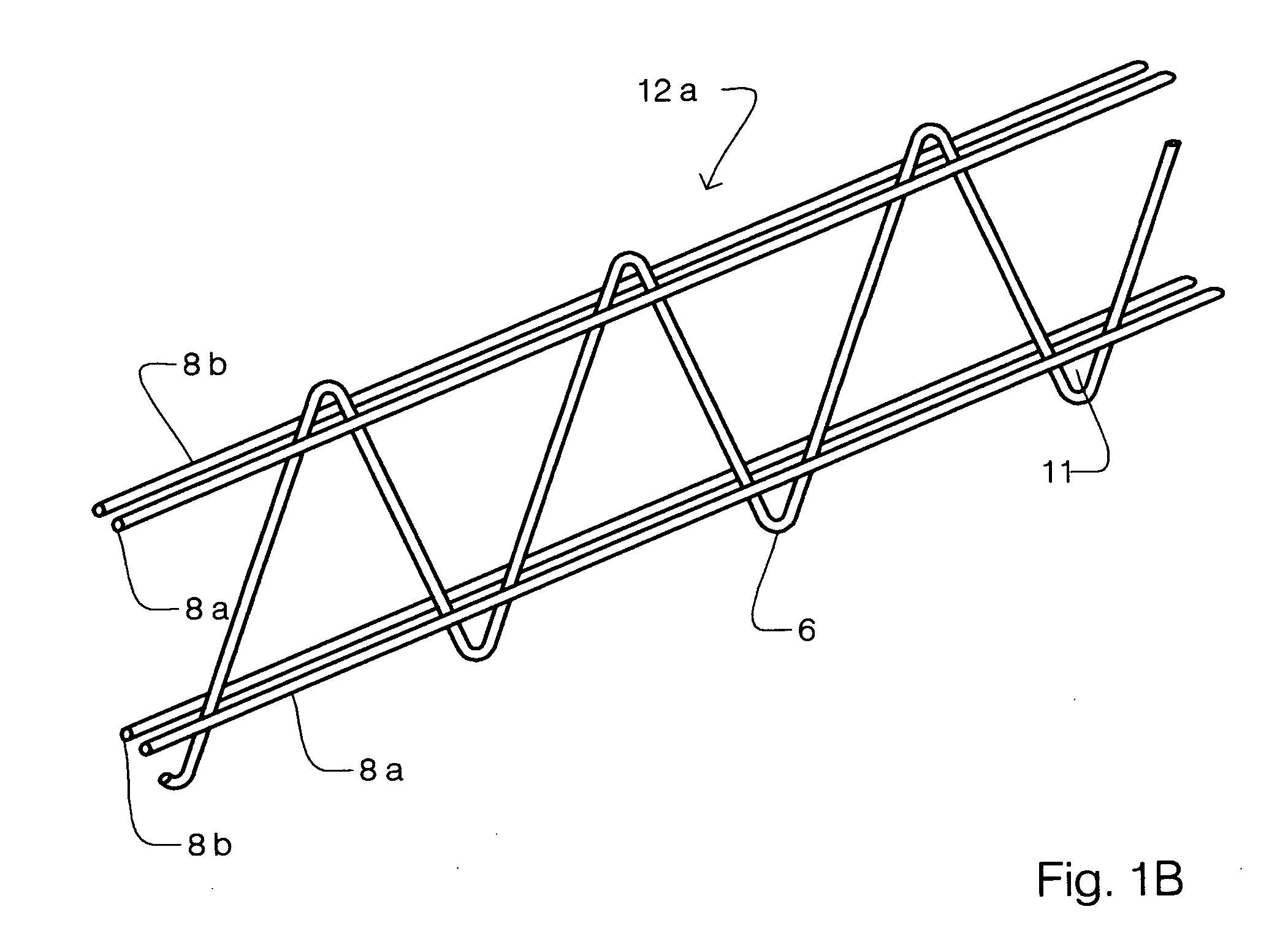
[0074] A preferred embodiment of the aperture 11 of the present invention is comprised of a continuous reinforcement element 7 shown in (FIG. 1A) bent to a curvilinear waveform forming vertices 6 and comprising a web 7 of a truss 12a (FIG. 1B) formed by affixing one or more chords 8a, 8b to said web 7 at a predetermined location such that each vertex 6 extends beyond the attachment location of cords 8a, 8b forming an aperture of predetermined size. An array of reinforcement comprised of a plurality of trusses 12a (FIG. 1B) are integrated into a space frame shown in (FIG. 1D1) of predetermined length, width, and thickness by the insertion and attachment of lateral reinforcement 8c,d of predetermined size through aligned apertures 11 of spaced trusses.

[0075] Truss 12a may be disposed in spatial relationships with its neighbor by elements of an insulative core shown in (FIG. 4A), whose grooved transverse faces 16 fit the central web area of trusses 12a. Space frame (FIG. 1...


PUM


Abstract

An aperture formed by one or more elements of a truss and utilized to form ductile connections with other reinforcement elements. Said aperture may be formed by the positioning, bending, weaving or sewing of one or more said elements. The trusses may be disposed in parallel or intersecting planes and may be connected by the utilization of said apertures on site or fabricated offsite. They may be assembled into structures or into modular or custom panels with which structures may be built, and embedded in cementations. Insulation and other mechanical systems may be incorporated into said truss and panel systems prior to embedment in cementations. Said aperture-forming trusses may also be used to incorporate prior art into structures with enhanced properties. The resulting interconnected systems of apertures, trusses, insulation and other systems generally are embedded in cementations to produce structures with superior ductility of interconnections and enhanced composite behavior.

Description

CROSS REFERENCES TO RELATED APPLICATIONS [0001] Not Applicable BACKGROUND [0002] 1. Field of Invention [0003] This invention relates to the design of framework for the reinforcement of structures, including reinforcement for cementations, more particularly, the invention relates to an aperture reinforcement device that girds and cinctures other reinforcement in order to enhance composite and ductile properties of reinforcement arrays. [0004] 2. Description of Prior Art [0005] U.S. Pat. No. 6,226,942 to Bonin; Pete J. (May 8, 2001) [0006] U.S. Pat. No. 6,418,686 to Record, (Jul. 16, 2002) [0007] U.S. Pat. No. 3,879,908 to Weisman, Victor P. (Apr. 29, 1975) [0008] U.S. Pat. No. 4,226,067 to Artzer, Richard, F. (Oct. 7, 1980) [0009] U.S. Pat. No. 4,576,372 to Grutsch; George A. (May 14, 1985) [0010] U.S. Pat. No. 4,530,191 to Boisbiuche; Arsene G. (Aug. 23, 1985) [0011] U.S. Pat. No. 4,624,089 to Dunker; Friedrich W. (Nov. 25, 1986) [0012] U.S. Pat. No. 4,660,341 to Holtz; Neal (Apr. 2...

Claims


Application Information

Patent Timeline
IPC IPC(8): E04H12/00E04BE04C3/00E04C5/06E04C5/065E04C5/16
CPCE04C5/04E04C5/0636E04C5/064E04C5/065E04C5/163E04C5/167
Inventor ANVICK, THEODORE E.CHADWICK, FORREST RYAN
Owner ANVICK THEODORE E
Why Eureka
Try Eureka