Light emitting display device and method of driving the same

Inactive Publication Date: 2006-06-29
ASAHI KOGAKU KOGYO KK
View PDF3 Cites 8 Cited by
  • Summary
  • Abstract
  • Description
  • Claims
  • Application Information

AI Technical Summary

Benefits of technology

[0013] Therefore, an object of the present invention is to provide a light emitting display device which maintains uniform luminance by using a simple driving system.

Problems solved by technology

However, the effectiveness of the EL device becomes deteriorates and the luminous efficiency of pixels of the EL device becomes different, as the emitting time elongated.
Accordingly, uniformity in the luminance is usually lacking on the display panel if it is used for a long time.
However, in this method the display panel has to be driven while the display panel is not used, therefore, the electrical power is unnecessarily consumed.
Furthermore, the output value of each pixel for all the pixels has to be integrated in order to confirm to what extent each pixel has deteriorated, therefore the process of this method becomes complicated.

Method used


Image

  • Light emitting display device and method of driving the same
  • Light emitting display device and method of driving the same
  • Light emitting display device and method of driving the same

Examples


Embodiment Construction

[0030] The present invention will be described below with reference to the embodiments shown in the drawings.

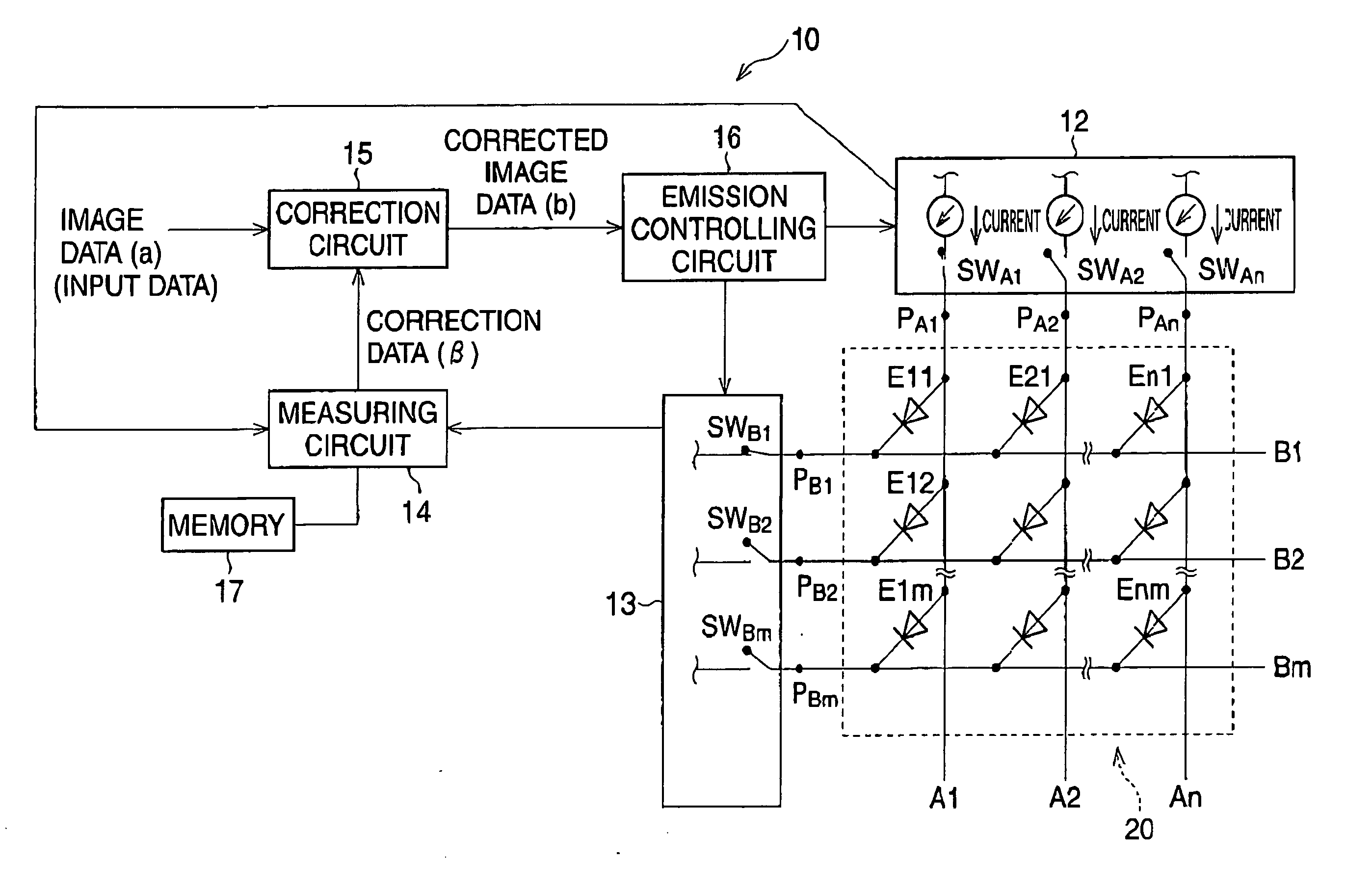
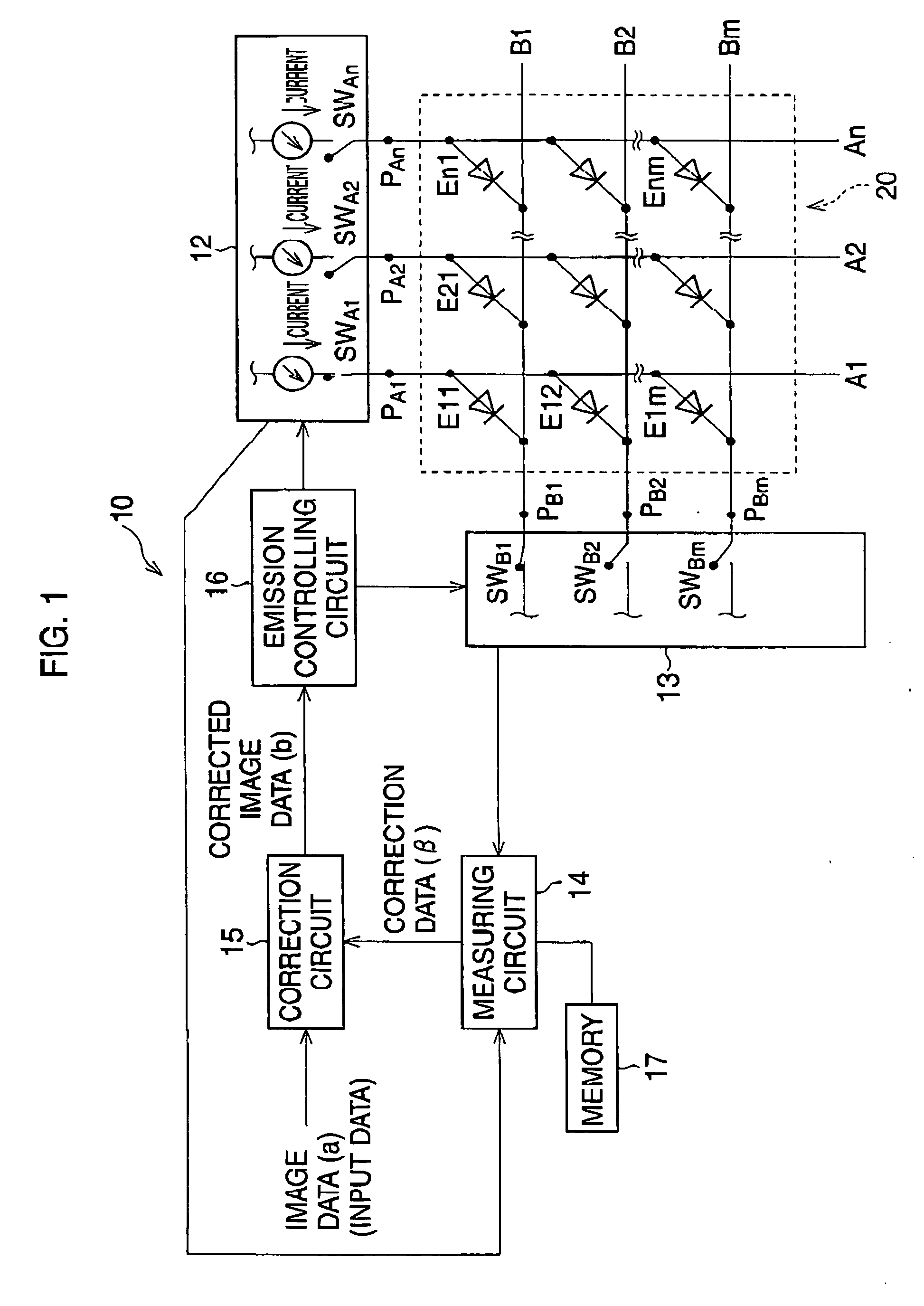
[0031]FIG. 1 is a block diagram, showing the light emitting display device to which a first embodiment of the present invention is applied.

[0032] The light emitting display device 10 has a display panel 20, which is driven by using the passive matrix driving method. The display panel 20 has a plurality of anode lines A1-An as the signal electrodes and a plurality of cathode lines B1-Bm as the scanning electrodes. The plurality of anode lines A1-An extending in the vertical direction, crosses the plurality of cathode lines B1-Bm extending in the horizontal direction.

[0033] The display panel 20 has an EL device, which is disposed between the plurality of anode lines A1-An and the plurality of cathode lines B1-Bm. The electric current is input to each part of the EL device at intersections of the anode lines A1-An and each of the cathode lines B1-Bm, so that the parts of the ...


PUM


Abstract

A unit quantity of electricity is input to each pixel of a plurality of pixels according to image data so that the each pixel emits a predetermined light. The luminance of the predetermined light per unit quantity of electricity is smaller as electric resistance value of each pixel become larger. A high resistance pixel having a relatively high electric resistance value or a low resistance pixel having a relatively low electric resistance value is detected among the plurality of pixels. The unit quantity of electricity is adjusted for at least one of the high resistance pixel and the low resistance pixel.

Description

BACKGROUND OF THE INVENTION [0001] 1. Field of the Invention [0002] The present invention relates to a light emitting display device having an emitting device such as an organic electroluminescent device. [0003] 2. Description of the Related Art [0004] Recently, light emitting display devices using organic electroluminescent devices (hereafter “EL device”) have been developed as the EL display devices. EL display devices have several superior properties for example, high response speed, wide angle field of vision, not needing back lighting, and occupying a small space. [0005] Conventionally, there are two methods of driving an EL display device, the passive matrix driving method and the active matrix driving method. [0006] The passive matrix display comprises a plurality of scanning electrodes and a plurality of signal electrodes which are crossed with the scanning electrodes. The pixels of the display are formed by a part of the EL device at the intersections of the scanning electr...

Claims


Application Information

Patent Timeline
IPC IPC(8): G09G3/06G09G3/32
CPCG09G3/3216G09G3/3225G09G2320/0285G09G2320/0295G09G2320/043
Inventor CHIBA, TORUSHIOKAWA, TAKANOBUSEKIYA, TAKAOMIKUBOTA, YUKIO
Owner ASAHI KOGAKU KOGYO KK
Why Eureka
Try Eureka