Exhaust gas analyzer

a gas analyzer and exhaust gas technology, applied in the field of exhaust gas analyzers, can solve the problems of large and expensive soot detectors, clogging of soot-containing portions, and affecting the measurement accuracy of soot, and achieves the effect of simple and low-cost arrangement, easy change and adjustment of dilution ratios

Inactive Publication Date: 2006-07-06
HORIBA LTD
View PDF14 Cites 24 Cited by
  • Summary
  • Abstract
  • Description
  • Claims
  • Application Information

AI Technical Summary

Benefits of technology

[0017] The present claimed invention intends to solve the above-mentioned problems concerning dilution in measuring the exhaust gas, more concretely, desired objects are mainly (1) to make it possible to obtain a dilution ratio necessary for soot concentration measurement with a simple and low-cost arrangement by making use of the SOF measuring system with focusing attention on that both concentration of SOF and concentration of soot are measured in measuring diluted particulate matters, (2) to pro

Problems solved by technology

However, since it is impossible for this method to collect the generating PM dynamically, there is a demand for a simple measurement instrument that is capable of a real-time continuous PM measurement in a step of research and development of an internal combustion engine.
This kind of a soot detector requires that the exhaust gas be diluted to concentration appropriate to the exhaust gas measurement because it is high sensitive, however, there are the following problems in diluting the exhaust gas.
However, in order to obtain the dilution ratio if the soot detector has an arrangement wherein a flow of the exhaust gas prior to dilution and a flow of the exhaust gas after dilution are measured respectively by the use of a venturi meter and the dilution ratio is calculated based on the flow ratios, the soot detector becomes large and costly.
However, if the exhaust gas as being sample gas or the diluent gas is forcefully fed or sucked by the use of, for example, a rotary pump in order for dilution, a bad influen

Method used


Image

  • Exhaust gas analyzer
  • Exhaust gas analyzer
  • Exhaust gas analyzer

Examples


Embodiment Construction

[0052] An exhaust gas analyzer in accordance with one embodiment of the present claimed invention will be described in detail with reference to the accompanying drawings.

(1) Overall Configuration of the Exhaust Gas Analyzer

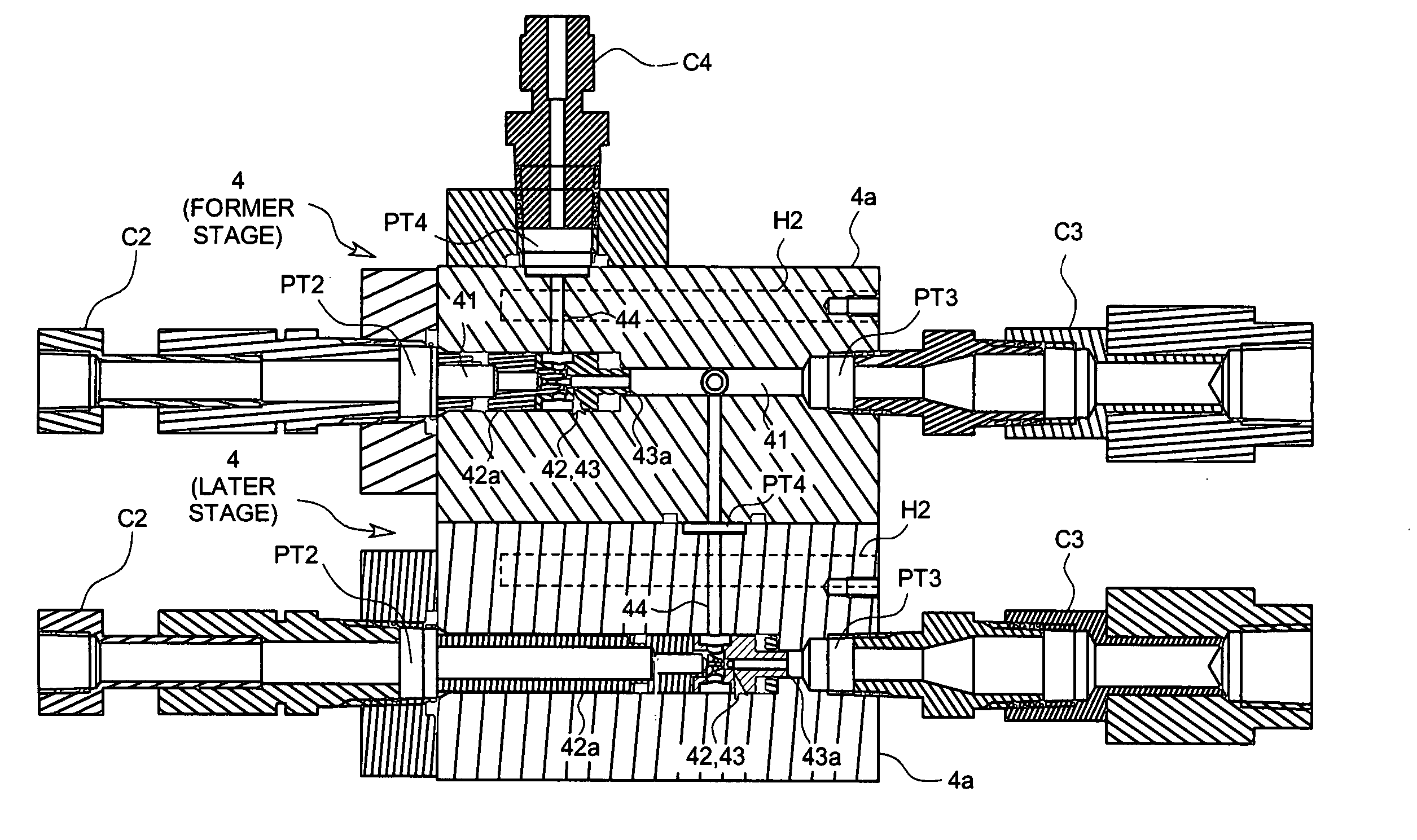
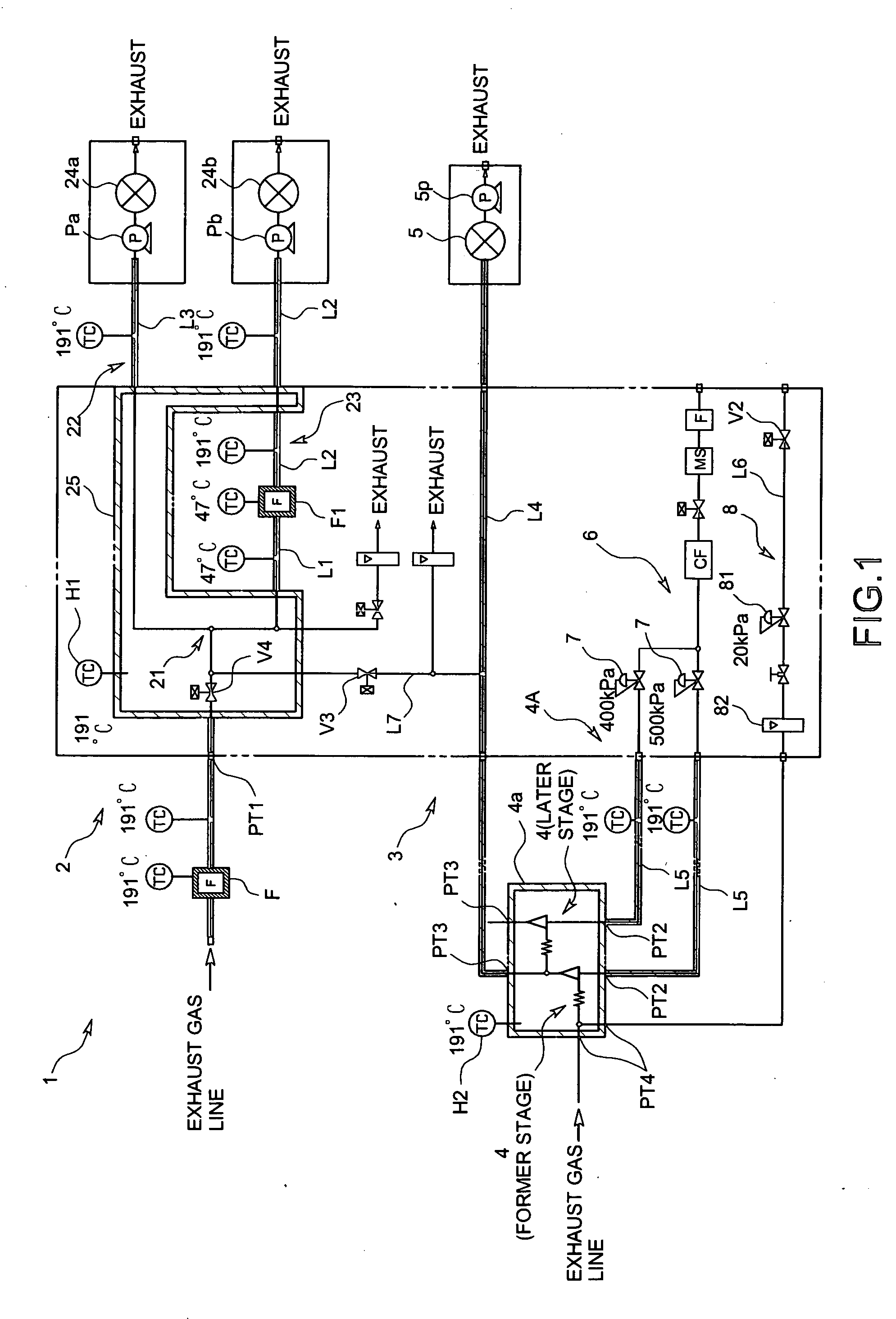
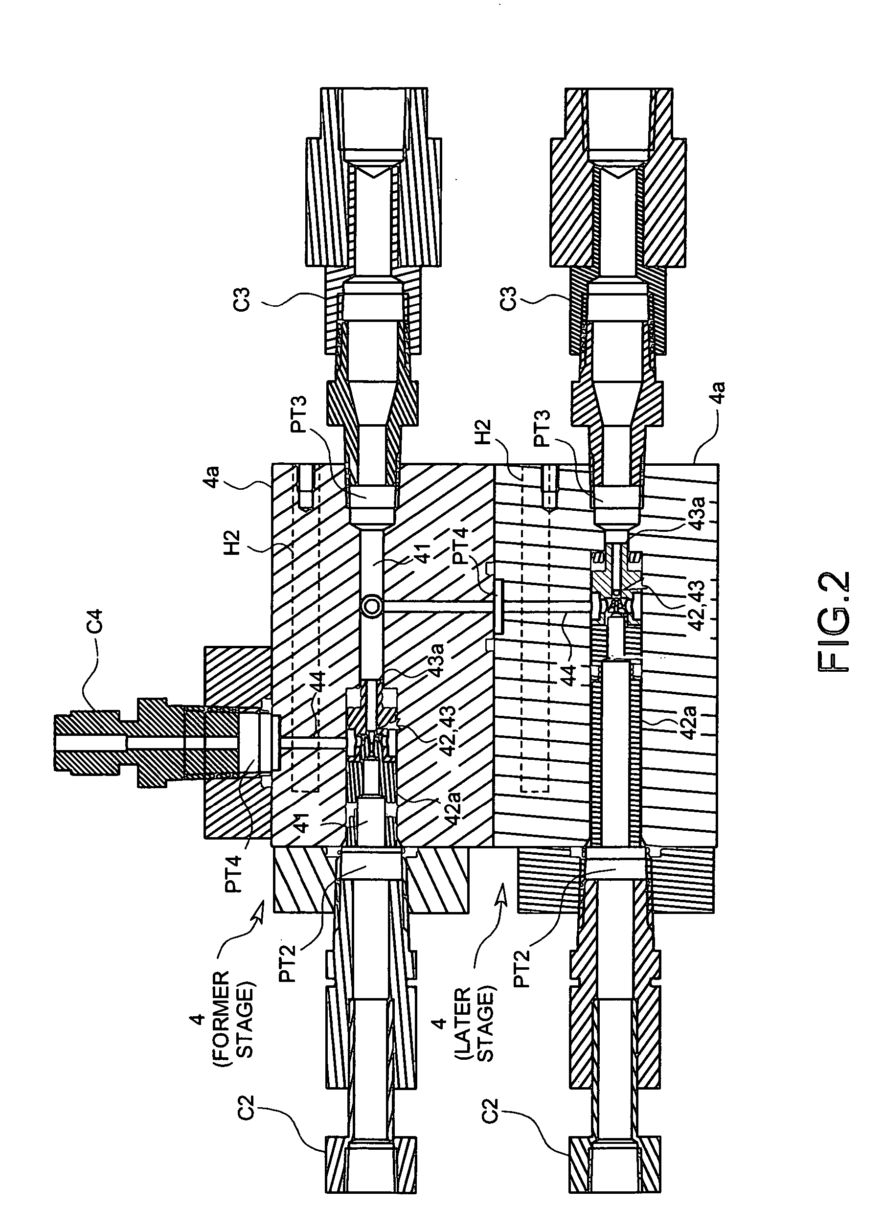
[0053] The exhaust gas analyzer 1 in accordance with this embodiment is to measure mass concentration of SOF (soluble organic fraction) and soot contained in exhaust gas of a diesel engine (not shown in drawings) as being an internal combustion engine and, as shown in FIG. 1, comprises an SOF measuring system 2 that can continuously measure mass concentration of SOF and a soot measuring system 3 that can continuously measure mass concentration of soot, each of which is connected in parallel with an exhaust gas line (not shown in drawings) to which a part or all of the exhaust gas is discharged from the diesel engine.

(2) SOF Measuring System

[0054] First, the SOF measuring 2 system will be explained.

[0055] The SOF measuring system 2 comprises, as shown in FIG...


PUM

PropertyMeasurementUnit
Temperatureaaaaaaaaaa
Pressureaaaaaaaaaa
Flow rateaaaaaaaaaa

Abstract

An SOF measuring system that can continuously measure SOF and a soot measuring system that can continuously measure soot are connected with an exhaust gas line. The soot measuring system comprises a diluter that selectively dilutes either one of the exhaust gas and standard gas whose hydrocarbon concentration is known with diluent gas and extrudes it. A dilution ratio adjusting device can adjust a dilution ratio of the diluter. A soot detector continuously detects soot in the exhaust gas or the standard gas diluted by the diluter. The SOF measuring system can be connected with the diluter so that an exhaust gas analyzer can measure the hydrocarbon concentration in the standard gas diluted by the diluter.

Description

BACKGROUND OF THE INVENTION [0001] 1. Field of the Invention [0002] This invention relates to an exhaust gas analyzer used for continuously measuring particulate matters (PM) included in exhaust gas of a diesel engine of, for example, a vehicle. [0003] 2. Background Art [0004] Minute particulate matters (PM) that might cause an adverse effect on the environment or human health are contained in exhaust gas of an internal combustion engine such as a diesel engine, and soot and soluble organic fraction (SOF) or the like are mixed in the particulate matters. [0005] In order to improve the internal combustion engine so as to reduce the particulate matters, it is necessary to measure the PM emissions accurately. According to a method for measuring exhaust gas that is publicly specified by the requirement of current laws and regulations, it is specified that the PM is collected by a filter and the collected PM is weighted on a microbalance. [0006] However, since it is impossible for this m...

Claims


Application Information

Patent Timeline
IPC IPC(8): G01N33/497B01F23/10
CPCG01N1/2252G01N33/0018G01N33/0022G01N2001/2264G01N2001/387
Inventor KUSAKA, TAKESHITANIGUCHI, AKIHIROOKADA, KAORUKUMAGAI, TATSUKI
Owner HORIBA LTD
Why Eureka
Try Eureka