Hydraulic controller for working machine

a working machine and hydraulic controller technology, applied in the direction of fluid couplings, servomotors, couplings, etc., can solve the problems of increasing the complexity and cost of the apparatus inevitably, economic undesirable, and the use of pilot pressure input switching valves, if provided specially for hydraulic devices, to reduce the uneven supply flow rate of each working hydraulic actuator, and reduce the occurrence of cavitation

Active Publication Date: 2007-03-22
KOBELCO CONSTR MASCH CO LTD
View PDF2 Cites 4 Cited by
  • Summary
  • Abstract
  • Description
  • Claims
  • Application Information

AI Technical Summary

Benefits of technology

[0008] It is an object of the present invention to provide a hydraulic controller for a working machine capable of remotely controlling a plurality of pilot-operated hydraulic devices provided in the working machine with a simple and low-cost arrangement.
[0011] In accordance with the present invention, since the pilot hydraulic pressure source and further the pilot pressure input switching valve are used in common for pilot pressure inputs to the plurality of pilot-operated hydraulic devices, it is possible to achieve remote control of the pilot-operated hydraulic devices while reducing the complexity and cost of the entire apparatus. In addition, it is possible to perform pilot pressure input switching control appropriately based on the operating state of the working machine and the pilot pressure input conditions set for the respective pilot-operated hydraulic devices.
[0019] In the case above, if the second pilot-operated hydraulic device has a pilot pressure input condition: a) a rotation driving speed of the hydraulic pump is equal to or less than a predetermined level, it is possible to reduce the occurrence of cavitation effectively when the hydraulic pump has a lower rotation driving speed. Also, if the device has a condition: b) a plurality of working hydraulic actuators including the specific working hydraulic actuator are driven simultaneously, it is possible to reduce the uneven supply flow rate to each working hydraulic actuator effectively.

Problems solved by technology

Therefore, the more the number of hydraulic devices, the more the number of pilot pressure input switching valves accompanying the devices, which increases the complexity and cost of the apparatus inevitably.
Particularly, in the case of less frequently used hydraulic devices, the use of a pilot pressure input switching valve, if provided specially for the hydraulic devices, becomes far less frequent, being economically undesirable.

Method used


Image

  • Hydraulic controller for working machine
  • Hydraulic controller for working machine
  • Hydraulic controller for working machine

Examples


Embodiment Construction

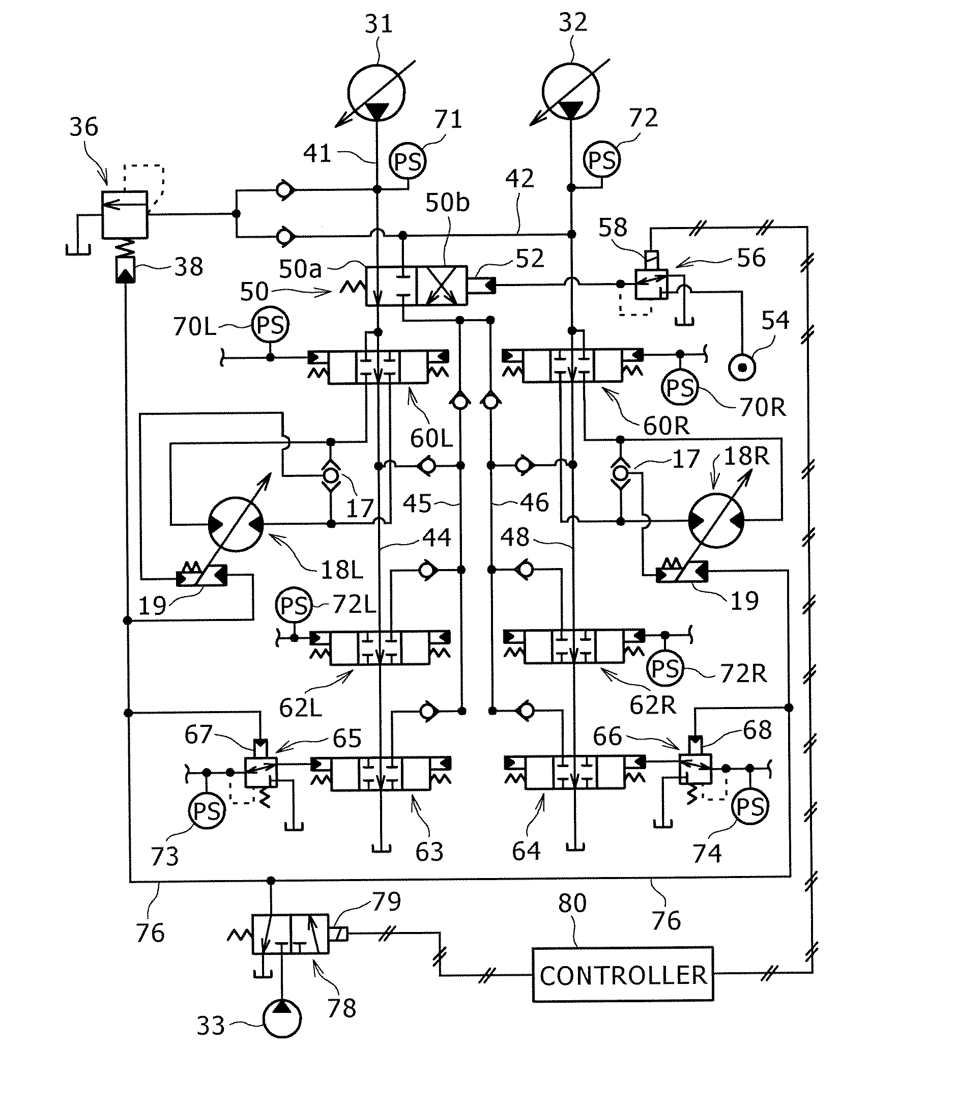
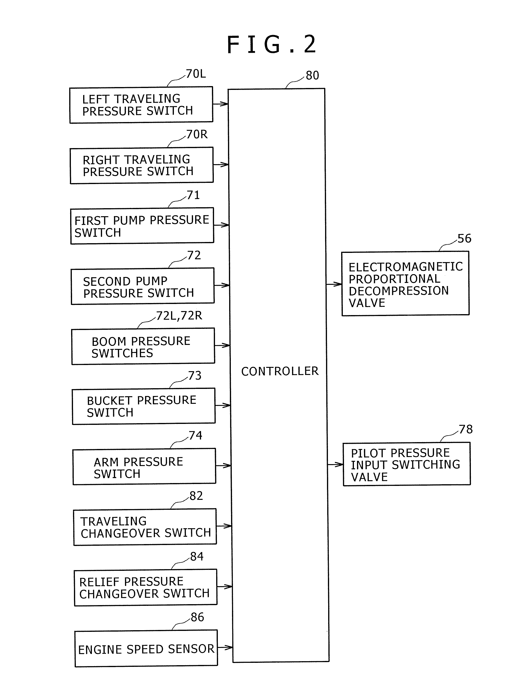
[0026] A preferred embodiment of the present invention will be described with reference to the accompanying drawings. It is noted that although the present embodiment is obtained by applying the present invention to a hydraulic excavator 10 shown in FIG. 6, the present invention can also be applied effectively to other working machines such as hydraulic cranes and crushing machines.

[0027] The hydraulic excavator 10 includes a lower traveling body 12 and an upper rotating body 14 mounted rotatably on the lower traveling body.

[0028] The lower traveling body 12 includes left and right traveling crawlers 16L and 16R, the traveling crawlers 16L and 16R including, respectively, traveling motors 18L and 18R as hydraulic motors for rotating the iron wheels of the crawlers.

[0029] In the hydraulic excavator 10, a boom 20 is provided hoistably on the upper rotating body 14 as a working attachment. An arm 22 is connected rotatably to the leading end of the boom 20. Further, a bucket 24 is at...


PUM


Abstract

There is provided a hydraulic controller for a working machine in which a pilot hydraulic pressure source is connected in common to a plurality of pilot-operated hydraulic devices each having a pilot pressure input unit, and a common pilot pressure input switching valve is adapted to control the switching between a pilot pressure input from the pilot hydraulic pressure source to each pilot pressure input unit and a relief of the input. The switching control of a pilot pressure input by the pilot pressure input switching valve is performed based on the operating state of the working machine and pilot pressure input conditions of the respective pilot-operated hydraulic devices.

Description

BACKGROUND OF THE INVENTION [0001] 1. Field of the Invention [0002] The present invention relates to an apparatus for controlling the operation of a plurality of pilot-operated hydraulic devices provided in a working machine. [0003] 2. Description of the Related Art [0004] As means for remotely controlling pilot-operated hydraulic devices provided in a working machine, there has been known an arrangement in which a pilot pressure input switching valve composed of an electromagnetic switching valve, etc. is provided between a pilot pressure input unit of the hydraulic devices and a pilot hydraulic pressure source, and the supply of the input signal of the pilot pressure to the pilot pressure input unit is switched by opening and closing the switching valve. [0005] For example, Japanese Patent Laid-Open No. 2002-5106 discloses a hydraulic circuit in which a solenoid valve (electromagnetic switching valve) is provided between a pilot pressure input unit (swash plate) of a capacity vari...

Claims


Application Information

Patent Timeline
Patent Type & Authority Applications(United States)
IPC IPC(8): F16D31/02
CPCE02F9/2239F15B2211/781F15B2211/329F15B2211/355F15B2211/41518F15B2211/50518F15B2211/528F15B2211/5753F15B2211/6054F15B2211/6309F15B2211/6316F15B2211/633F15B2211/6346F15B2211/6355F15B2211/665F15B2211/6658F15B2211/67F15B2211/7058F15B2211/71F15B2211/7135F15B2211/763F15B11/166
Inventor TOJI, YUTAKAYAMAZAKI, YOICHIROYAMASHITA, KOJIOKA, HIDEKAZUUEDA, KOJI
Owner KOBELCO CONSTR MASCH CO LTD
Why Eureka
Try Eureka