
Inflatable keel floor chamber for inflatable kayaks

a technology of inflatable kayaks and floor chambers, which is applied in the field of inflatable kayaks using inflatable keel floor chambers, can solve the problems of poor performance and poor tracking capability of inflatable kayaks, and achieve the effect of less elasti

Inactive Publication Date: 2006-07-06
THE COLEMAN CO INC
View PDF27 Cites 30 Cited by
  • Summary
  • Abstract
  • Description
  • Claims
  • Application Information

AI Technical Summary

Benefits of technology

[0009] The improved keeled hull improves the tracking characteristics of inflatable kayaks while reducing the below waterline drag compared to some prior inflatable kayaks.

Problems solved by technology

However, such kayaks typically have poor tracking capabilities and suffer from poor performance when compared to “hard shell” kayaks.

Method used


Image

  • Inflatable keel floor chamber for inflatable kayaks
  • Inflatable keel floor chamber for inflatable kayaks
  • Inflatable keel floor chamber for inflatable kayaks

Examples


Embodiment Construction

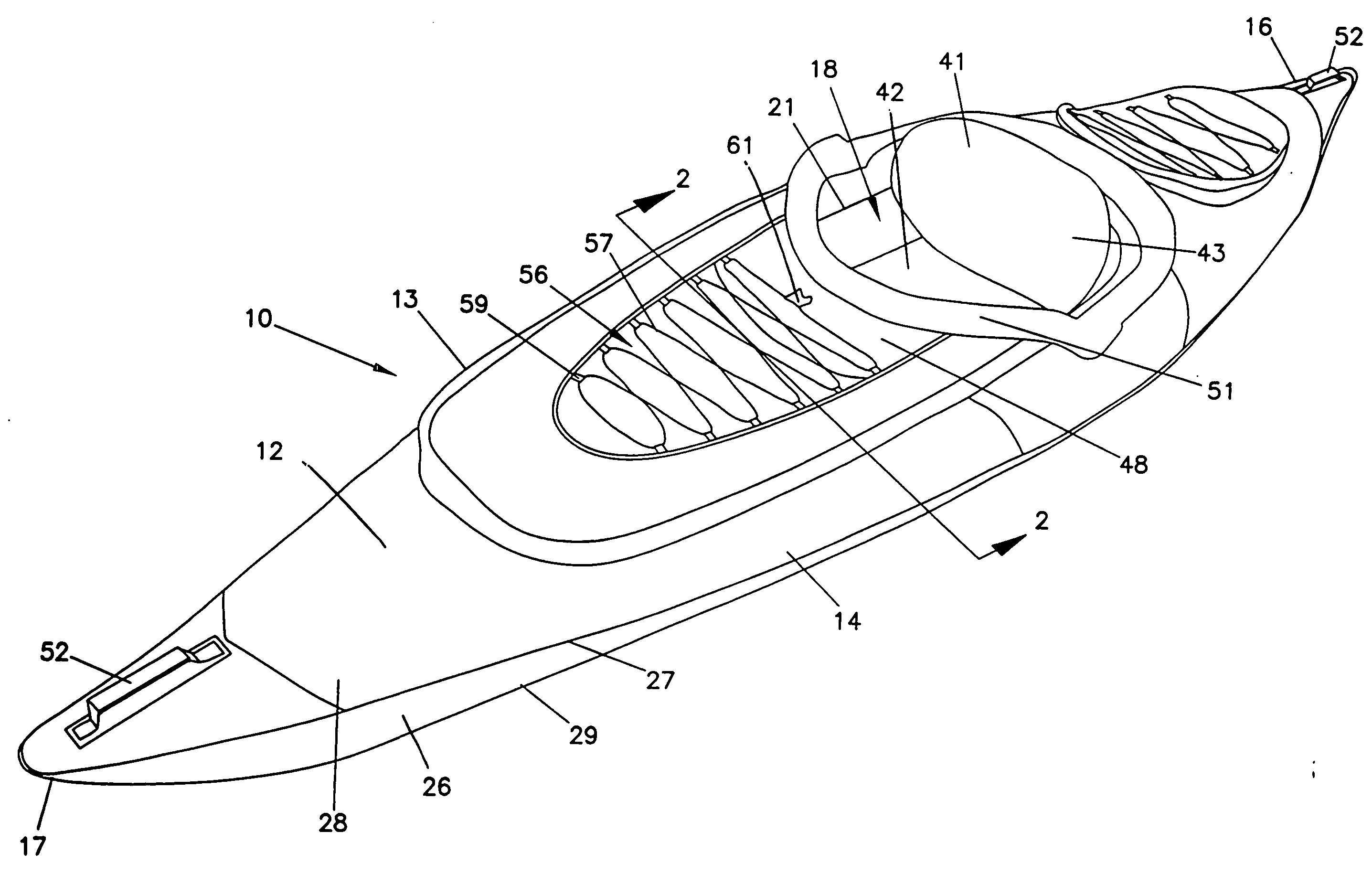
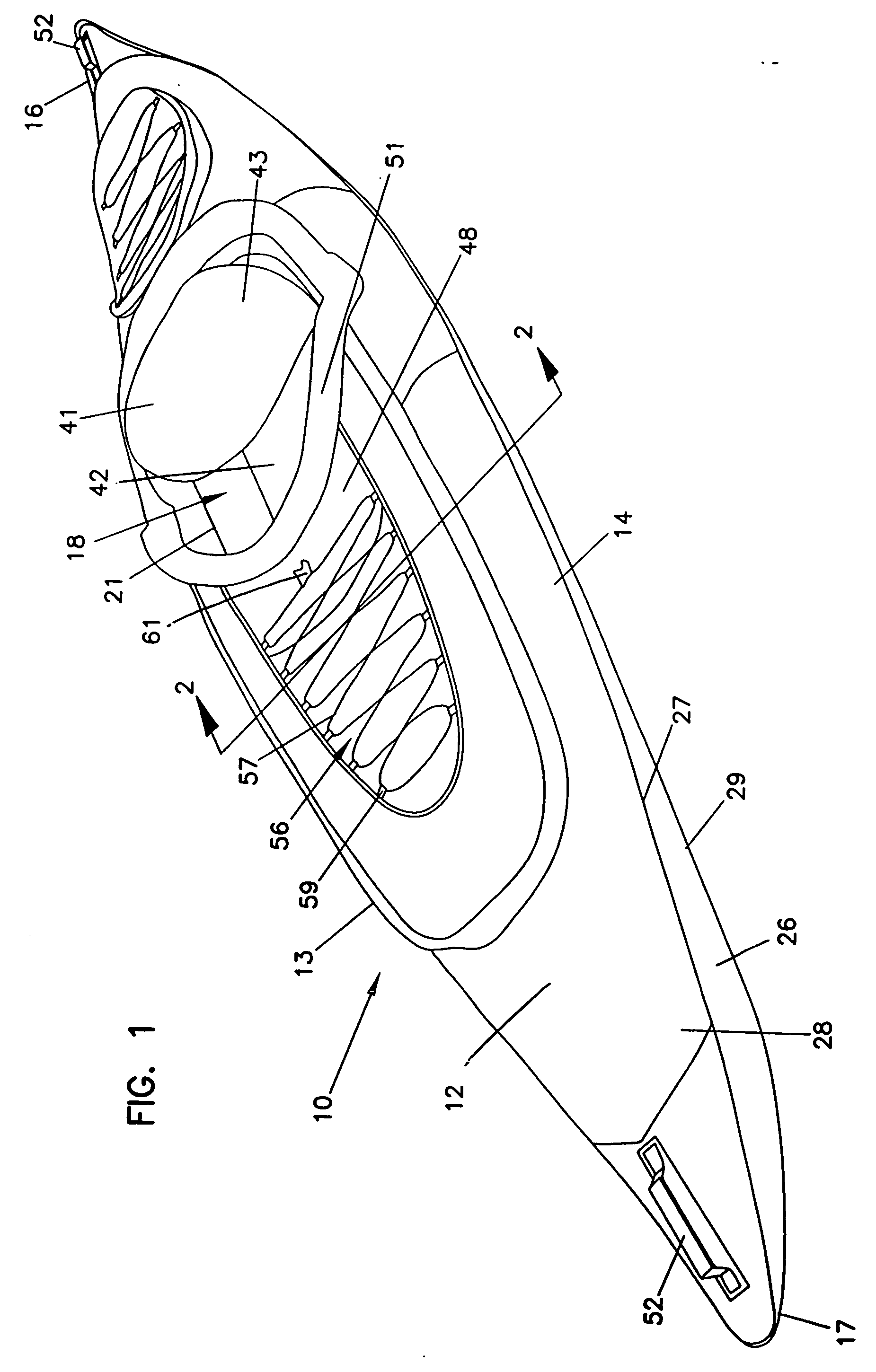
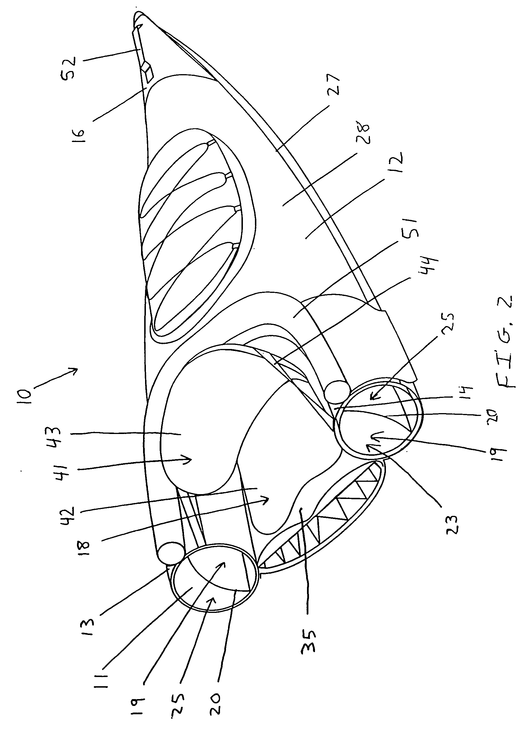
[0029] In FIGS. 1-3, the kayak 10 is shown. The kayak 10 includes a fore section 17 and an aft section 16. A passenger compartment 18 is located between the fore section 17 and the aft section 16.

[0030] The performance limitations of inflatable kayaks have been attributed to their floor designs. Many prior-art kayaks utilize an inflatable floor chamber that is thin and flat on both sides. These floor chambers resemble an air mattress with top and bottom sheets having roughly the same surface area. This basic construction performs poorly because it tends to create a “barge effect” during operation. The “barge effect” increases the drag on an inflatable kayak while paddling through water due to the width of the kayak below the water line. Moreover, the floors of certain prior art inflatable kayaks do not effectively support the weight of many users. For example, there is a tendency for the floor shape to dip down under the user's weight. This has the effect of further increasing drag...


PUM


Abstract

The inflatable kayak includes an inflatable peripheral structure defining at least one buoyancy chamber having elongated side sections that come together at a fore section and a aft section to form a passenger compartment. An inflatable floor cushion supports a floor of the passenger compartment. The floor cushion includes a top wall, a bottom wall, and at least one side gusset. The surface area of the top wall is less than the surface area of the bottom wall. A plurality of elongated, I-beam baffles extends between the top wall and the bottom wall. Each I-beam baffle has a midpoint, between the fore section and aft section, and an end, wherein the height of at least one I-beams baffle measured from the junction of the top wall to the junction of the bottom wall is greater at the midpoint of the baffle than at the end of the baffle. In another embodiment, the inflatable kayak includes an inflatable floor cushion wherein the distance between at least two I-beam baffles along the top wall is less than the distance between at least two I-beam baffles along the bottom wall.

Description

BACKGROUND OF THE INVENTION [0001] 1. Field of the Invention [0002] This invention relates generally to boats, kayaks and, more particularly, to inflatable kayaks using an inflatable keel floor chamber. [0003] 2. Description of the Prior Art [0004] Kayaks have been constructed in a number of different ways, from a variety of materials. Conventional kayaks are characterized as “hard shell” kayaks because they incorporate rigid frames. Hard shell kayaks perform well because their long and slim design allows for superior tracking and speed performance. [0005] Traditionally, kayaks have been constructed from wood. However, kayaks have also been constructed from other materials like molded fiberglass or other rigid plastic materials. These embodiments have allowed kayaks to become lighter and more portable than traditional wood kayaks. [0006] As portable equipment became increasingly desirable, inflatable kayaks were developed. Inflatable kayaks have been available commercially from comp...

Claims


Application Information

Patent Timeline
Patent Type & Authority Applications(United States)
IPC IPC(8): B63B7/00
CPCB63B35/71B63B41/00B63B34/22B63B34/26
Inventor TOUSSI, AFSHINLOU, CLAUDE T.S.
Owner THE COLEMAN CO INC
Learn More