Single-and-continual shot changeover device for a nailing gun

a changeover device and nailing gun technology, applied in the field of nailing guns, can solve the problems of finger skin damage, unfavorable handling, etc., and achieve the effect of easy shifting, stable and accurate handling of the changeover devi

Inactive Publication Date: 2006-07-06
BENTLEY FASTENING TOOLS
View PDF4 Cites 8 Cited by
  • Summary
  • Abstract
  • Description
  • Claims
  • Application Information

AI Technical Summary

Benefits of technology

[0007] A single-and-continual shot changeover device for a nailing gun in the invention includes a trigger shaft positioned in an interior of a trigger body, a trigger inner member pivotally connected to an intermediate fitting stage of the trigger shaft, two slide shaft stages at two sides of the intermediate fitting stage, and two springs and two press buttons respectively fitting around the two slide shaft stages. The press buttons are pushed normally outward by the springs to be secured at a lower one of two lengthwise points of the two sidewalls of the trigger body, and possible to be pressed elastically inward to separate from the trigger body and then shifted upward to be secured at an upper one of the two lengthwise points for changing the position of the two press buttons so as to shift the trigger inner member up and down and separate or not from the safety connect rod, and therefore, changing firing a single shot to continual shot or vice versa. As the two press buttons are pressed elastically inward manually and easily for shifting the trigger inner member for firing a single or continual shot, so the handling the changeover device is very stable and accurate.

Problems solved by technology

However, in handling the conventional changeover device for a nailing gun, it cannot be done with only one hand, but it must be done with the left hand holding the grip of the nailing gun or with the nailing gun put down for properly turned over, and with the right hand pulling out the rotatable button 123 beside the trigger 1 rotated for adjusting and then released.
So its handling is not so convenient, and in addition, a user is obliged to use a large force to a finger in pulling out and rotating the rotatable button 123, with its exposed portion of the rotatable button 123 being very small for avoiding accidental collision to be rotated.
Therefore, the finger may be liable to be damaged on its skin in its handling.

Method used


Image

  • Single-and-continual shot changeover device for a nailing gun
  • Single-and-continual shot changeover device for a nailing gun
  • Single-and-continual shot changeover device for a nailing gun

Examples


Embodiment Construction

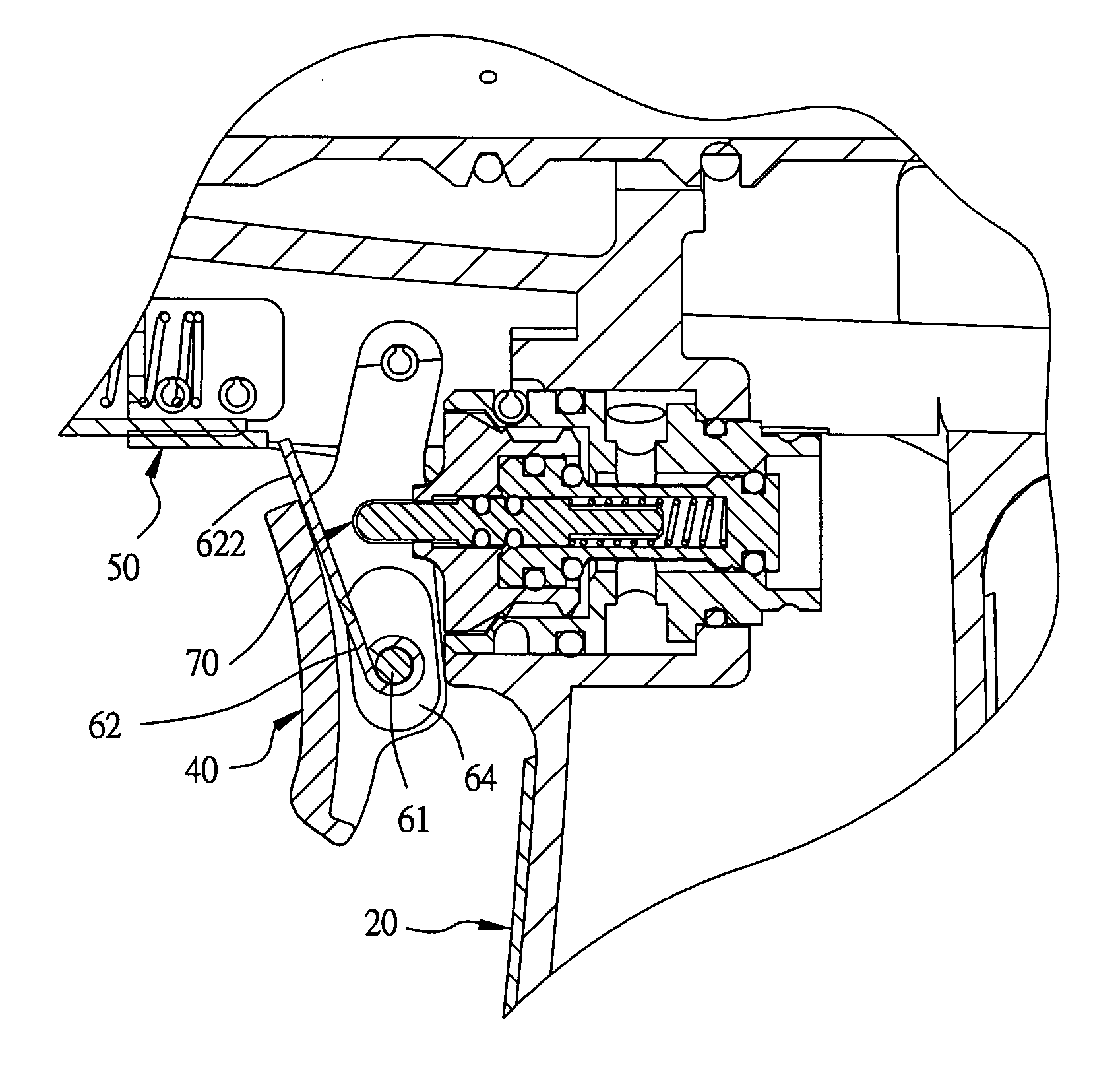
[0021] A preferred embodiment of a single-and-continual shot changeover device for a nailing gun in the present invention, as shown in FIGS. 4, 5 and 6, is constructed almost in the same way as the conventional one, except that the grip 20 of the gun body 30 of a nailing gun has a trigger body 40 pivotally connected therewith and facing to a safety connect rod 50, and the single-and-continual shot changeover device. 60 is combined with the trigger body 40 to be moved properly by the safety connect rod 50, and an air valve switch 70 for firing a shot. At the same time, the changeover switch 60 includes a trigger shaft 61, a trigger inner member 62, two springs 63 and two press buttons 64, as shown in FIGS. 7 and 8.

[0022] The trigger body 40 is provided with an inner space 41 facing on the air valve switch 70, two side-walls defining the inner space 41 and a lengthwise slide slot 42 respectively formed in each sidewall, a limit groove 421 formed at two sides of each slide slot 42, an...


PUM

PropertyMeasurementUnit
resiliencyaaaaaaaaaa
resilienceaaaaaaaaaa
forceaaaaaaaaaa

Abstract

A single-and-continual shot changeover device for a nailing gun includes a trigger shaft positioned in an interior of a trigger body, a trigger inner member pivotally connected with an intermediate fitting stage of the trigger shaft, which also has two slide shaft stages at two sides of the fitting stage for two springs and two press buttons to fitting around respectively. The two press buttons are elastically pushed to shift outward to engage one of two—an upper and a lower—grooves of the two sidewalls of the trigger body. When the two press buttons are pressed inward, the trigger inner member can be shifted up and down to let the press buttons secured at either of the two limit grooves by means of the trigger shaft. Then the trigger inner member is controlled to separate or not from the safety connect rod for changing firing a single shot or continual shot.

Description

BACKGROUND OF THE INVENTIN [0001] 1. Field of the Invention [0002] This invention relates to a nailing gun, especially to one provided with a single-and-continual shot changeover device possible to be operated with easiness, steadiness and without fail. [0003] 2. Description of the Prior Art [0004] A conventional single-and-continual shot changeover device 10 for a nailing gun shown in FIGS. 1 and 2 is arranged between an air valve switch and a safety connect rod, including a trigger 11, an eccentric adjust rod 12 and an actuating member 13. The trigger 11 is positioned at one side of the gun body to face to the air valve switch, and the eccentric adjust rod 12 consists of a press plate 121, an eccentric rod 122, a rotatable button 123 and a recover spring 124. The eccentric rod passes through the trigger 11, fixed eccentrically between the press plate 121 and the rotatable button 123, with the actuating member 13 having one end pivotally connected with the eccentric rod 122. Normal...

Claims


Application Information

Patent Timeline
Patent Type & Authority Applications(United States)
IPC IPC(8): F41B11/00
CPCB25C1/043B25C1/046
Inventor WANG, BRIAN
Owner BENTLEY FASTENING TOOLS
Why Eureka
Try Eureka